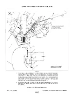
NOTE
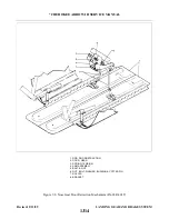
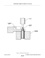
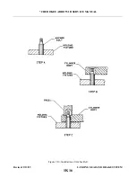
When installing a new wing, it will be necessary to back drill two (2) holes
0.250 inch and countersink 100° x .499 through the spar cap. (Screw head
should be flush with spar.) Use hole in the support bracket has a guide in
the drilling.
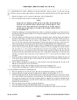
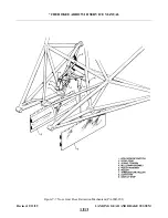
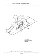
2. Ascertain that the upper and lower links (28 and 33) are assembled with downlock hook (30),
retraction fitting (21), etc. attached, and the through travel of the links and downlock hook
clearance checked according to Paragraph 7-24.
3. Attach the upper link to the swivel stud of the support fitting and secure with bolt, bushing,
washer, nut and cotter pin.
4. The actuating cylinder rod end bearing (46) and lower side brace link (33) may be attached
respectively to the retraction fitting (21) and gear housing during the adjustment of the landing
gear.
d. Ascertain that the landing gear is lubricated per Lubrication Chart.
e.
Check adjustment of the landing gear per Paragraph 7-26.
f.
Check alignment of the wheel per Paragraph 7-27.
g. Install the access plate on the underside of the wing and remove the airplane from jacks.
7-26. ADJUSTMENT OF MAIN LANDING GEAR.
a.
Place the airplane on jacks. (Refer to Jacking, Section II.)
b. Level the airplane laterally and longitudinally. (Refer to Leveling, Section II.)
c.
Disconnect the gear door actuating rods at either the door or the housing, as desired, by removing the
rod attachment bolt. Secure the door out of the way.
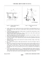
d. Adjust the gear oleo housing to obtain a vertical position with the airplane level (90 degrees to
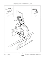
horizontal). To do this, set 90 degrees on a bubble protractor, place the protractor along the side of the
gear piston tube and adjust the end bearing of the lower side brace link allowing the bubble of the
protractor to center when the end bearing is connected to the gear housing. This should allow an angle
of 83 +/- 1/2 degrees between the gear housing and the spar cap of the wing. Place a bushing on each
side of the end bearing and secure with bolt, washer and nut.
e.
Check that the rod end has sufficient thread engagement in the end bearing, align the flat sides of the
bearing casting with the flat side of the bearing and tighten the jam nut.
NOTE
With reference to the lower and upper side brace links, a maximum of .026
inch end play is allowed considering a load of 30 +/- 5 lbs. applied at the
wheel axle with the strut completely extended. The load should be applied
inboard and outboard to obtain maximum movement for determination of
end play.
Revised: 2/13/89
1K1
* CHEROKEE ARROW III SERVICE MANUAL
LANDING GEAR AND BRAKE SYSTEM
Summary of Contents for ARROW III
Page 4: ...THIS PAGE INTENTIONALLY LEFT BLANK 1A4...
Page 12: ...THIS PAGE INTENTIONALLY LEFT BLANK 1A12...
Page 94: ...Figure 4 2 Wing Installation Revised 2 13 89 1D22 CHEROKEE ARROW III SERVICE MANUAL STRUCTURES...
Page 171: ...lH3 INTENTIONALLY LEFT BLANK...
Page 172: ...lH4 INTENTIONALLY LEFT BLANK...
Page 286: ...THIS PAGE INTENTIONALLY LEFT BLANK Revised 2 13 89 2A8...
Page 528: ...INTENTIONALLY LEFT BLANK 2K10 THRU 2L24 2K10...

