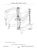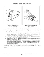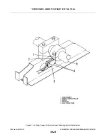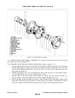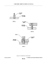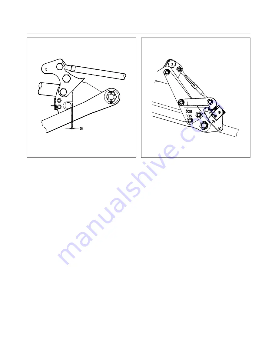
Figure 7-12. Adjustment of Nose
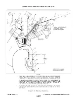
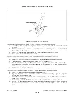
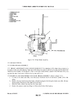
Figure 7-13. Adjustment of Main Gear
Gear Down Limit Switch
Down Limit Switch
7-34. ADJUSTMENT OF NOSE GEAR DOWN LIMIT SWITCH. The gear down limit switch is mounted on
the horizontal support tube of the engine mount that runs between the tight attachment points of the gear
housing and upper drag link.
a.
Ascertain that the gear is down and locked.
b. The down limit switch should actuate only after the leading edge of the downlock hook, when moving
to the locked position, has passed the downlock roller by .06 of an inch. (Refer to Figure 7-12.)
Position the hook at this location in relation to the roller by moving the actuator piston manually
toward the up position. The downlock spring may be disconnected, if desired.
c.
Loosen the attachment screws of the actuator located on the downlock hook and move it toward the
switch until it is heard to actuate. Retighten the actuator screws.
d. Manually move the hook from the locked to the unlocked position and ascertain that the switch
actuates at the correct location of the hook.
e.
Retract and extend the gear electrically by turning the master switch on, raising the emergency gear
extension lever and moving the gear selector handle to the up position. As the gear begins to retract,
the green light below the selector should go out and the red gear unsafe light at the top of the
instrument panel should come on.
7-35. ADJUSTMENT OF MAIN GEAR UP LIMIT SWITCH. A gear up limit switch is located in each wheel
well above the door hinge. There is no adjustment of these switches other than check that the gear, when
retracting, will actuate the switch within .88 of an inch of full up. Switch operation turns the red gear unsafe
light out.
Revised: 2/13/89
1K6
* CHEROKEE ARROW III SERVICE MANUAL
LANDING GEAR AND BRAKE SYSTEM
Summary of Contents for ARROW III
Page 4: ...THIS PAGE INTENTIONALLY LEFT BLANK 1A4...
Page 12: ...THIS PAGE INTENTIONALLY LEFT BLANK 1A12...
Page 94: ...Figure 4 2 Wing Installation Revised 2 13 89 1D22 CHEROKEE ARROW III SERVICE MANUAL STRUCTURES...
Page 171: ...lH3 INTENTIONALLY LEFT BLANK...
Page 172: ...lH4 INTENTIONALLY LEFT BLANK...
Page 286: ...THIS PAGE INTENTIONALLY LEFT BLANK Revised 2 13 89 2A8...
Page 528: ...INTENTIONALLY LEFT BLANK 2K10 THRU 2L24 2K10...

