e.
The piston(s) may be removed by injecting low air pressure in the cylinder fluid inlet and forcing the
piston from the housing.
f.
Check anchor bolt for wear.
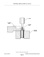
g. Remove anchor bolt by the following procedure:
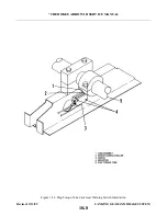
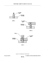
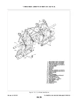
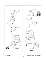
1. Position cylinder assembly on a holding fixture. (Refer to Figure 7-19.)
2. Use a suitable arbor press to remove the anchor bolt from the cylinder head.
7-55. CLEANING, INSPECTION AND REPAIR OF WHEEL BRAKE ASSEMBLY.
a.
Clean the assembly with a suitable solvent and dry thoroughly.
b. Check the wall of the cylinder housing and piston for scratches, burrs, corrosion, etc, that may damage
O-rings.
c.
Check the general condition of the brake bleeder screw and lines.
d. Check the brake disc for wear, grooves, scratches, or pits. Wear of the disc should not be less than
0.205 of an inch at its thinnest point. A single groove or isolated grooves up to 0.031 of an inch deep
would not necessitate replacement, but a grooving of the entire surface would reduce lining life and
should be replaced. Should it be necessary to remove the wheel disc, refer to paragraph 7-48.
e.
Lining may be removed from the backing plates by drilling or punching out the old rivets and
installing a new set using the proper rivets and a rivet set that will properly stake the lining and form a
correct flair of the rivet.
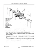
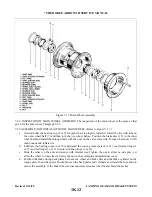
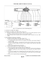
7-56. ASSEMBLY AND INSTALLATION OF WHEEL BRAKE ASSEMBLY. (Refer to Figure 7- 18.)
a.
Lubricate the piston O-ring(s) with fluid MIL-H-5606 and install on piston(s). Slide the piston in
cylinder housing until flush with surface of housing.
b. Slide the lining pressure plate onto the anchor bolts of the housing.
c.
Slide the cylinder housing assembly on the torque plate of the gear.
d. Position the lining back plate between the wheel and brake disc. Install the bolts and torque to 40 inch
pounds to secure the assembly.
e.
Connect the brake line to the brake cylinder housing.
f.
Bleed the brake system as described in paragraph 7-69.
NOTE
In order to obtain optimum service life from newly installed brake linings,
they must be properly conditioned. To condition the brake linings, perform a
minimum of six light pedal effort braking applications from 25 to 40 mph.
Allow the brake discs to partially cool between stops.
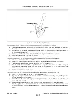
7-57. BRAKE MASTER CYLINDER. (Hand Parking Brake.)
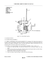
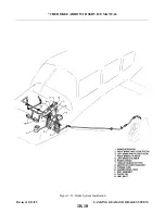
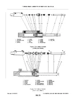
7-58. REMOVAL OF BRAKE MASTER CYLINDER. (Refer to Figure 7-21.)
a.
To remove the brake master cylinder (8), first disconnect the inlet supply line (13) from the fitting at
the top of the cylinder and allow fluid to drain from the reservoir and line into a suitable container.
b. Disconnect the pressure line from the fitting at the bottom of the cylinder and allow fluid to drain from
the cylinder line.
c.
d. Disconnect the base of the cylinder from its mounting bracket by removing the attachment bolt
e.
The handle assembly (6) may be removed by removing the attachment bolt assembly that secures the
handle to its mounting bracket.
Revised: 2/13/89
1K14
* CHEROKEE ARROW III SERVICE MANUAL
LANDING GEAR AND BRAKE SYSTEM
Summary of Contents for ARROW III
Page 4: ...THIS PAGE INTENTIONALLY LEFT BLANK 1A4...
Page 12: ...THIS PAGE INTENTIONALLY LEFT BLANK 1A12...
Page 94: ...Figure 4 2 Wing Installation Revised 2 13 89 1D22 CHEROKEE ARROW III SERVICE MANUAL STRUCTURES...
Page 171: ...lH3 INTENTIONALLY LEFT BLANK...
Page 172: ...lH4 INTENTIONALLY LEFT BLANK...
Page 286: ...THIS PAGE INTENTIONALLY LEFT BLANK Revised 2 13 89 2A8...
Page 528: ...INTENTIONALLY LEFT BLANK 2K10 THRU 2L24 2K10...

