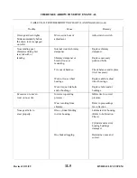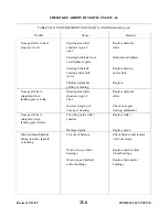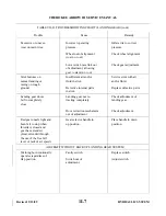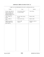
NOTE
Fluid level in the reservoir must be maintained to prevent air from entering
in the line.
g. Tighten both wheel bleeders.
h. Pull hand brake until a firm handle is maintained.
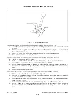
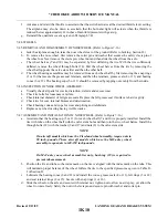
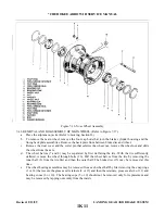
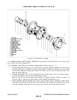
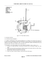
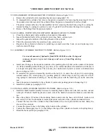
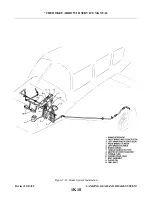
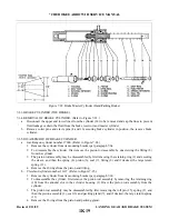
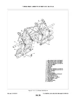
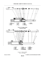
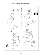
7-71. BRAKE BLEEDING PROCEDURE (Pressure). (Refer to Figure 7-26.)
a.
Place a small clear plastic hose on the vent tube of the brake reservoir and place a second small clear
plastic hose on the bleeder fitting on one main landing gear. Place the open ends of these tubes in a
suitable container to collect the fluid overflow. Open the bleeder fitting one or two turns.
b. On the other main gear, slide the hose of the pressure unit over the bleeder fitting then open the fitting
one or two turns and pressure fill the brake system with MIL-H-5606 fluid.
c.
With fluid continually flowing through the brake system, SLOWLY and together actuate the hand
brake and the toe brake pedal of the side being bled several times to purge the cylinders of air. On dual
brake installations, both right and left pedals must be actuated.
NOTE
By watching the fluid pass through the plastic hose at the fluid reservoir
and the bleeder fitting on the gear being bled, it can be determined whether
any air is left in the system. If air bubbles are evident, filling of the system
shall be continued until all the air is out of the system and a steady flow of
fluid is obtained. Should the brake handle remain spongy, it may be
necessary to disconnect the bottom of the toe brake cylinders (next to the
pedal) and rotating the cylinder horizontally or even above horizontal and
by use of the hand brake alone, purge the air from the system.
d. Close the open bleeder fitting on the gear being bled. Close the open bleeder fitting to which the
pressure hose is attached; then close the pressure unit and remove the hoses from the bleeder fittings.
Check the brakes for proper pedal pressure. Replace the caps over the bleeder fittings.
NOTE
It may be necessary to remove any trapped air in the top of the wheel brake
unit by applying pressure to the system with the brake hand lever and slowly
opening the bleeder and release the hand lever.
e.
Repeat this procedure, if necessary, on the other gear.
f.
Drain excess fluid from the reservoir to fluid level line with a syringe.
Revised: 2/13/89
1K23
* CHEROKEE ARROW III SERVICE MANUAL
LANDING GEAR AND BRAKE SYSTEM
Summary of Contents for ARROW III
Page 4: ...THIS PAGE INTENTIONALLY LEFT BLANK 1A4...
Page 12: ...THIS PAGE INTENTIONALLY LEFT BLANK 1A12...
Page 94: ...Figure 4 2 Wing Installation Revised 2 13 89 1D22 CHEROKEE ARROW III SERVICE MANUAL STRUCTURES...
Page 171: ...lH3 INTENTIONALLY LEFT BLANK...
Page 172: ...lH4 INTENTIONALLY LEFT BLANK...
Page 286: ...THIS PAGE INTENTIONALLY LEFT BLANK Revised 2 13 89 2A8...
Page 528: ...INTENTIONALLY LEFT BLANK 2K10 THRU 2L24 2K10...

