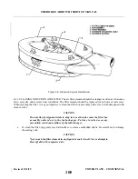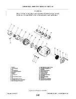
8-15. INSTALLATION OF PROPELLER GOVERNOR.
a.
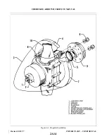
Clean the mounting pad and the governor drive shaft thoroughly.
b. Coat the mounting gasket with Dow Corning release agent or equivalent.
c.
Lubricate the drive shaft with engine oil and install the governor on the mounting pad.
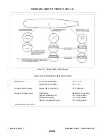
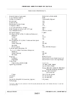
d. Tighten the mounting bolts evenly and tighten to a final torque as shown in Figure 8-5.
e.
Connect the control cable to the control arm. Check to be sure the attachment bolt does not contact the
governor body while moving the control arm through its full travel. Clearance should be .03 minimum.
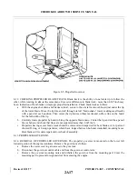
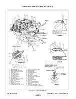
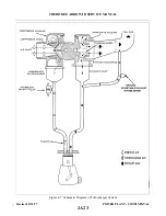
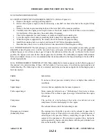
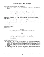
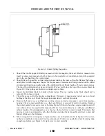
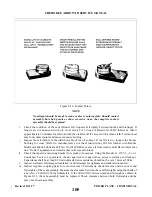
8-16. RIGGING AND ADJUSTMENT OF PROPELLER GOVERNOR. (Refer to Figure 8-5.)
a.
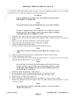
Start engine; park 90° to wind direction and warm in normal manner.
b. To check high RPM, low pitch setting, move the propeller control all the way forward. At this position
the governor speed control arm should be against the high RPM fine adjusting screw. With the throttle
full forward, observe engine RPM, which should stabilize between 2500 and 2575 RPM. A takeoff
must be conducted during which the engine RPM should reach 2575 RPM and remain steady.
c.
If the engine RPM does not read 2575 RPM in flight, the high RPM setting must be adjusted as
follows:
1. Land, shut down the engine and remove lower cowl access plug (See Figure 8-1.)
2. Adjust the governor by means of the fine adjustment screw for 2575 RPM. To do this, loosen the
high RPM fine adjustment screw locknut and turn the screw in a clockwise direction to decrease
engine speed or in a counterclockwise direction to increase engine speed.
NOTE
One revolution of the fine adjustment screw will increase or decrease the
engine speed approximately 20 RPM.
3. Repeat Step b to ascertain proper RPM setting.
4. After setting the proper high RPM adjustment, run the self-locking nut on the fine adjustment
screw against the base projection to lock, and install the lower cowl access plug.
d. With the high RPM adjustment complete, the control system should be adjusted so that the governor
control arm will contact the high RPM stop when the cockpit control knob is .032 to .047 of an inch
from its full forward stop. To adjust the control knob travel, disconnect the control cable end from the
control arm; loosen the cable end jam nut and rotate the end to obtain the desired level clearance.
Reconnect the cable end and tighten jam nut. (Lower cowl must be removed to accomplish this
adjustment.)
e.
It is usually only necessary to adjust the high RPM (low pitch) setting of the governor control system,
as the action automatically takes care of the positive low RPM (high pitch) setting.
Revised: 8/31/77
2A18
CHEROKEE ARROW III SERVICE MANUAL
POWER PLANT - CONTINENTAL
Summary of Contents for ARROW III
Page 4: ...THIS PAGE INTENTIONALLY LEFT BLANK 1A4...
Page 12: ...THIS PAGE INTENTIONALLY LEFT BLANK 1A12...
Page 94: ...Figure 4 2 Wing Installation Revised 2 13 89 1D22 CHEROKEE ARROW III SERVICE MANUAL STRUCTURES...
Page 171: ...lH3 INTENTIONALLY LEFT BLANK...
Page 172: ...lH4 INTENTIONALLY LEFT BLANK...
Page 286: ...THIS PAGE INTENTIONALLY LEFT BLANK Revised 2 13 89 2A8...
Page 528: ...INTENTIONALLY LEFT BLANK 2K10 THRU 2L24 2K10...

