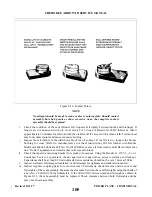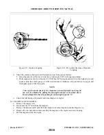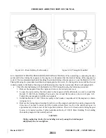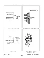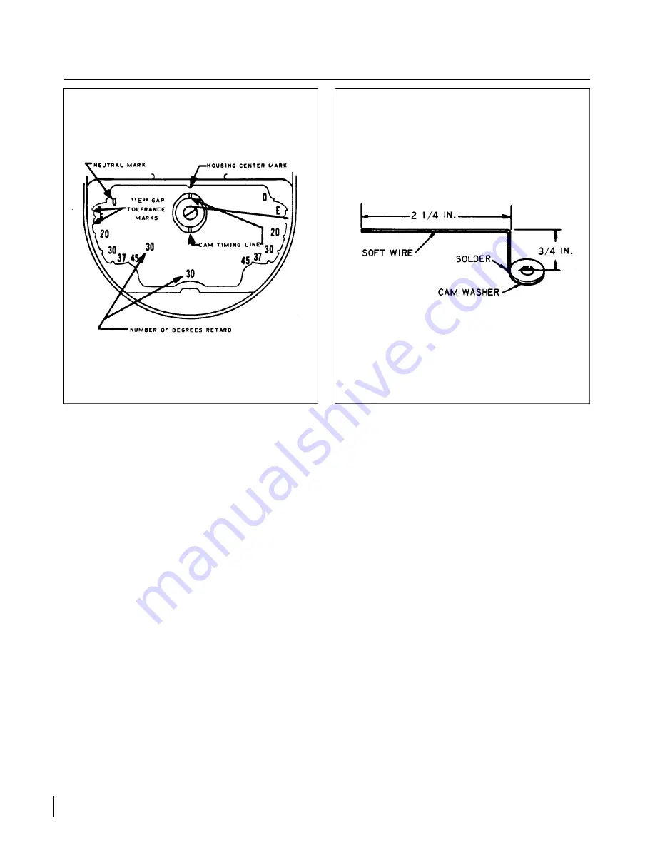
Figure 8-15. Cast-in Timing Marks
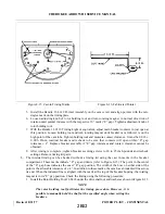
Figure 8-16. Fabricated Pointer
5. Install the Bendix 11-8149 Pointer Assembly on the cam screw and align pointer with the zero
degree mark on the timing plate.
6. Loosen adjusting knob of rotor holding tool and turn rotating magnet in normal direction of
rotation until pointer indexes with the respective 10° mark (“E” gap). Tighten adjustment knob of
rotor holding tool.
7. With the Bendix 11-9110 Timing Light or equivalent, adjust main breaker contacts to just open at
this position. Loosen holding tool and turn rotating magnet until breaker cam follower is on the
high point of the cam lobe. Tighten holding tool and measure contact clearance. It must be 0.018 ±
0.006. If not, readjust breaker and recheck to be sure that contacts will open within “E” gap
tolerance ± 4°. Replace breaker assembly if “E” gap tolerances and contact clearance cannot be
obtained.
8. After timing is complete, tighten breaker securing screws to 20 to 25 inch-pounds and recheck
settings. Remove timing kit parts.
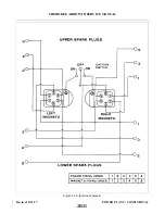
b. The internal timing can be checked without a timing kit using the cast in marks in the breaker
compartment. These marks indicate “E” gap and limits (refer to Figure 8-15). The point in the center
of the “E” gap boss indicates the exact “E” gap position. The width of the boss on either side of the
point is the allowable tolerance of ± 4°. In addition to these marks, the cam has an indented line across
its end. When the indented line is aligned with the mark at the top of the breaker housing, the rotating
magnet is in its “E” gap position. Check the timing using the following procedure:
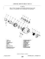
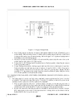
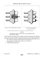
1. Install the Rotor Holding Tool 11-8465 under the drive shaft nut and washer as shown in Figure 8-13.
NOTE
The rotor holding tool facilitates the timing procedure. However, it is
possible to manually hold the shaft at the specified angle when setting the
breakers.
Revised: 8/31/77
2B12
CHEROKEE ARROW III SERVICE MANUAL
POWER PLANT - CONTINENTAL
Summary of Contents for ARROW III
Page 4: ...THIS PAGE INTENTIONALLY LEFT BLANK 1A4...
Page 12: ...THIS PAGE INTENTIONALLY LEFT BLANK 1A12...
Page 94: ...Figure 4 2 Wing Installation Revised 2 13 89 1D22 CHEROKEE ARROW III SERVICE MANUAL STRUCTURES...
Page 171: ...lH3 INTENTIONALLY LEFT BLANK...
Page 172: ...lH4 INTENTIONALLY LEFT BLANK...
Page 286: ...THIS PAGE INTENTIONALLY LEFT BLANK Revised 2 13 89 2A8...
Page 528: ...INTENTIONALLY LEFT BLANK 2K10 THRU 2L24 2K10...

