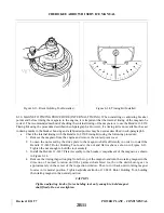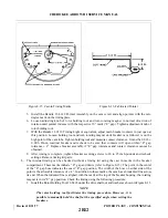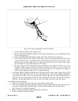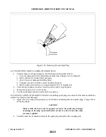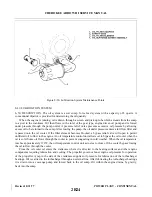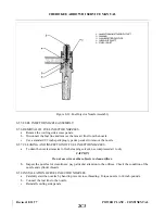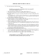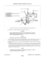
8-51. OIL FILTER REPLACEMENT. (Refer to Figure 8-30.) The oil filter element should be replaced after
each 50 hours of engine operation. The filter element is mounted on the lower portion of the engine accessory
case. Replace the filter element as follows:
a.
Remove the lockwire between the nut on the filter and the oil filter adapter and unscrew the filter
element.
b. Before installing a new filter, lubricate the gasket on the filter with engine oil.
c.
Torque the filter 18 to 20 foot-pounds or 3/4 to 1 full turn after the gasket makes contact.
CAUTION
Do not over torque.
d. Run the engine and check for oil leaks; then install lockwire between nut on filter and adapter.
8-52. ENGINE FUEL SYSTEM.
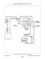
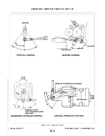
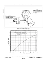
8-53. DESCRIPTION. The fuel injection system is a multi-nozzle, continuous flow, altitude compensating
system that regulates fuel flow to match engine operating conditions. The system consists of an engine driven
fuel pump, a throttle body, a fuel manifold valve and fuel discharge nozzles.
The engine driven fuel pump is a positive displacement, rotary vane type pump with an integral vapor
separator and altitude compensating aneroid valve.
The throttle body consists of a rotary valve metering unit attached to an air throttle that controls the flow of
air to the engine. The position of the cam shaped edge of the rotary valve across the fuel delivery port and
engine driven pump controls the fuel flow to the manifold valve and nozzles, thus controlling the fuel-air ratio.
The fuel manifold valve is the central point for dividing fuel to the individual cylinders. A diaphragm and
plunger valve within the manifold valve raises or lowers by fuel pressure to open or close the individual fuel
supply ports simultaneously.
The fuel discharge nozzles are an air bleed type nozzle with a calibrated orifice. A nozzle is installed in the
cylinder head outside each intake valve for each cylinder.
8-54. FUEL INJECTION SYSTEM MAINTENANCE.
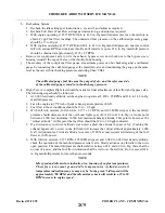
a.
Check all attaching parts for tightness.
b. Check all fuel lines for leaks, evidence of damage, or chafing by metal to metal contact.
c.
Check control connections, levers, and linkages for safety.
d. Inspect nozzles for cleanliness with particular attention to air screens and orifices. Use a standard 1/2
inch spark plug type deep socket to remove nozzles. Do not remove shield to clean air screens. Do not
use wire or other object to clean orifices. To clean nozzles, remove from engine and immerse in fresh
cleaning solvent. Use compressed air to dry.
e.
Unscrew strainer plug from fuel injection control valve and clean screen in solvent. Reinstall, safety,
and check for leaks.
f.
During periodic lubrication, add a drop of engine grade oil on each end of the air throttle shaft and at
each end of the linkage between the air throttle and fuel metering valve.
NOTE
Do not use any form of thread compound on fuel line fittings. Use only a
fuel soluble lubricant such as engine oil.
Revised: 8/31/77
2C1
CHEROKEE ARROW III SERVICE MANUAL
POWER PLANT - CONTINENTAL
Summary of Contents for ARROW III
Page 4: ...THIS PAGE INTENTIONALLY LEFT BLANK 1A4...
Page 12: ...THIS PAGE INTENTIONALLY LEFT BLANK 1A12...
Page 94: ...Figure 4 2 Wing Installation Revised 2 13 89 1D22 CHEROKEE ARROW III SERVICE MANUAL STRUCTURES...
Page 171: ...lH3 INTENTIONALLY LEFT BLANK...
Page 172: ...lH4 INTENTIONALLY LEFT BLANK...
Page 286: ...THIS PAGE INTENTIONALLY LEFT BLANK Revised 2 13 89 2A8...
Page 528: ...INTENTIONALLY LEFT BLANK 2K10 THRU 2L24 2K10...

