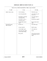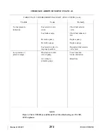
1. Press battery master switch ON. Check the VAC OFF annunciator illuminates.
2. Press VAC OFF/AUX ON annunciator switch. Ensure that AUX ON annunciator illuminates and
VAC OFF annunciator goes out. Observe that the vacuum gauge indicates between 4.8 and 5.2 in.
Hg.
3. Press VAC OFF/AUX ON annunciator switch to cycle it to the OFF position. Ensure that AUX
ON annunciator goes out and VAC OFF annunciator illuminates.
4. Press the battery master switch to OFF.
c.
Removal of Auxiliary Vacuum Pump.
WARNING
Verify that the battery master switch is in the OFF position.
CAUTION
The auxiliary vacuum pump and motor are one sealed assembly and must
be removed and replaced with another sealed assembly. The elapsed time
indicator is matched to the pump/motor assembly and must be removed and
replaced with the pump/motor assembly as one unit. Insulate and secure all
electrical leads that remain loose, if replacement is not installed
immediately.
1. Remove the top cowling.
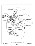
2. Disconnect hoses from pump/motor assembly.
3. Disconnect electrical leads at terminals of the pump/motor assembly.
4. Insulate and secure disconnected electrical leads.
5. Loosen the band clamps and remove pump/motor from firewall brackets.
6. Locate the elapsed time indicator under the right instrument panel; disconnect the electrical leads.
7. Remove the elapsed time indicator.
8. Insulate and secure the electrical leads at the elapsed time indicator.
9. If a replacement auxiliary pump is not installed now, place protective plugs or caps over open ends
of vacuum hoses and secure them. Install the top cowling.
d. Installation of Auxiliary Vacuum Pump Assembly.
WARNING
Verify that the battery master switch is OFF.
CAUTION
Never install an auxiliary pump assembly that has been dropped or
damaged. The matched elapsed time indicator must be installed with the
matched pump/motor assembly.
1. Remove temporary insulators and connect elapsed time indicator to two-pin connector on the leads
coming from the back of the switch, at rear right side of instrument panel.
2. Secure elapsed time indicator to wire harness with a strap (zip strip). Ensure that elapsed time
indicator can be easily located and inspected.
Revised: 2/13/89
2F17
CHEROKEE ARROW III SERVICE MANUAL
INSTRUMENTS
Summary of Contents for ARROW III
Page 4: ...THIS PAGE INTENTIONALLY LEFT BLANK 1A4...
Page 12: ...THIS PAGE INTENTIONALLY LEFT BLANK 1A12...
Page 94: ...Figure 4 2 Wing Installation Revised 2 13 89 1D22 CHEROKEE ARROW III SERVICE MANUAL STRUCTURES...
Page 171: ...lH3 INTENTIONALLY LEFT BLANK...
Page 172: ...lH4 INTENTIONALLY LEFT BLANK...
Page 286: ...THIS PAGE INTENTIONALLY LEFT BLANK Revised 2 13 89 2A8...
Page 528: ...INTENTIONALLY LEFT BLANK 2K10 THRU 2L24 2K10...

