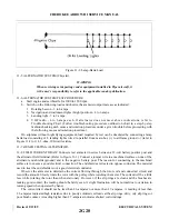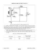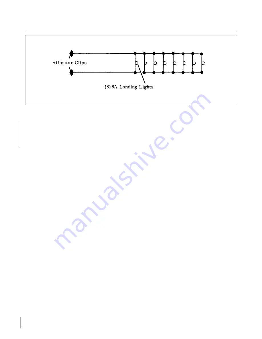
Figure 11-2. Lamp-Bank Load
11-5. ALTERNATOR SYSTEM (Chrysler).
WARNING
When servicing or inspecting vendor equipment installed in Piper aircraft, it
is the user’s responsibility to refer to the applicable vendor publication.
11-6. ALTERNATOR SYSTEM TEST PROCEDURE.
a.
Start engine and set throttle for 1000 to 1200 rpm.
b. Switch on the following loads and observe the ammeter output increase as indicated:
1. Rotating beacon - 3 to 6 amps.
2. Navigation and instrument lights (bright position) - 4 to 6 amps.
3. Landing light - 7 to 9 amps.
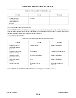
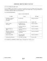
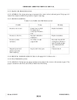
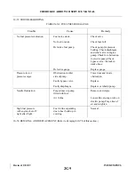
4. VHF radio - 4 to 6 amps each. If alternator does not meet above indications, refer to
Troubleshooting Chart. (Follow troubleshooting procedure outlined on chart in a step-by-step
fashion checking each cause and isolation procedure under a given trouble before proceeding with
the following cause and isolation procedure.)
On airplanes without night flying equipment, load required by test can be simulated by connecting a lamp
bank load consisting of 8 landing lights wired in parallel from main bus (+) to airframe ground (-) (refer to
Figure 11-2) or 14, 3-ohm, 100-watt resistors.
11-7. BENCH TESTING ALTERNATOR.
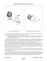
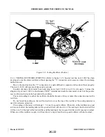
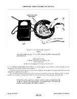
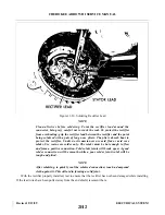
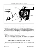
11-8. FIELD CURRENT DRAW. Connect a test ammeter in series between a 12-volt battery positive post and
the alternator field terminal. (Refer to Figure 11-3.) Connect a jumper wire to a machined surface on one of the
alternator end shields (ground) and to the negative battery post. The reason for connecting to the machined
surface is to ensure a good electrical connection. The end shields are treated to oppose corrosion. The material
used to treat the end shields is not a good electrical conductor.
Observe the ammeter to determine the current flowing through the rotor coil and connected circuit and
record the amount. Slowly rotate the rotor with the pulley while watching the meter. The current will be a little
less while rotating the rotor than when stationary. However, if the slip rings are clean and the brushes are
making good contact, the reading should be fairly even. A slight fluctuation will be normal due to variation in
turning speed when operated by hand.
The current draw should not be less than 2.3-amperes nor more than 2.7-amperes. A reading of less than
2.3-amperes indicated high resistance due to poorly soldered coil leads at the slip rings, dirty, oily slip rings or
poor brush contact. A reading higher than 2.7-amperes indicates shorted coil windings.
Revised: 2/13/89
2G20
CHEROKEE ARROW III SERVICE MANUAL
ELECTRICAL SYSTEM
Summary of Contents for ARROW III
Page 4: ...THIS PAGE INTENTIONALLY LEFT BLANK 1A4...
Page 12: ...THIS PAGE INTENTIONALLY LEFT BLANK 1A12...
Page 94: ...Figure 4 2 Wing Installation Revised 2 13 89 1D22 CHEROKEE ARROW III SERVICE MANUAL STRUCTURES...
Page 171: ...lH3 INTENTIONALLY LEFT BLANK...
Page 172: ...lH4 INTENTIONALLY LEFT BLANK...
Page 286: ...THIS PAGE INTENTIONALLY LEFT BLANK Revised 2 13 89 2A8...
Page 528: ...INTENTIONALLY LEFT BLANK 2K10 THRU 2L24 2K10...

