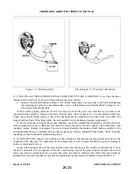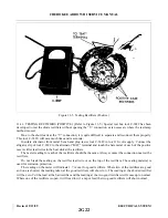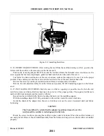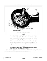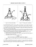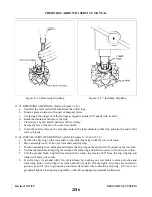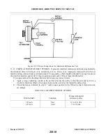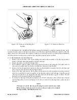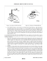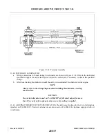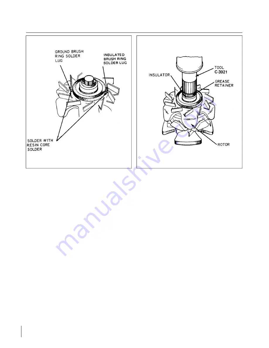
Figure 11-18. Solder Points
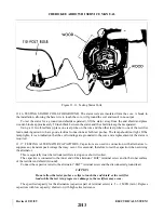
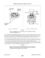
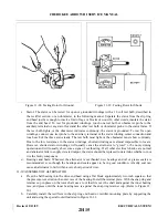
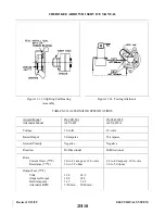
Figure 11-19. Installing Retainer
CAUTION
Under no circumstance use acid core solder. A short circuit may result and
corrosion will definitely occur.
11-25. INSTALLING GREASE RETAINER. (Refer to Figure 11-19.) If the solder connection where the rotor
field coil lead is soldered to the insulated brush ring lug has a sharp point or if the blob solder is excessive,
smooth with a scraper or file before installing the grease retainer insulator. If smooth, place fibre insulator on
shaft and press the retainer (cupped side to end of shaft) on the shaft with tool C-3921 in an arbor press.
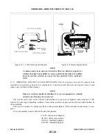
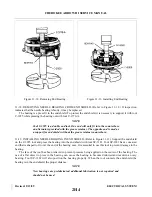
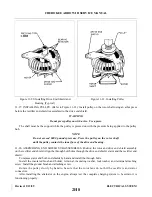
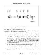
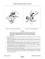
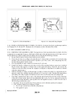
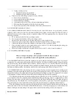
11-26. INSTALLING DRIVE END BEARING. (Refer to Figure 11-20.) Insert the sealed drive end bearing in
the drive end shield and install the bearing retainer. Install the washers and nuts to hold the bearing in place on
all early production. Snap the spring steel retainer fingers in place on all later production models.
If the rotor and its components require no service, position the bearing and the drive end shield assembly
on the rotor shaft and while supporting the parts on the end of the rotor shaft, press the bearing and end shield
assembly in position on the rotor shaft using an arbor press and tool C-3858.
CAUTION
Make sure that the bearing is installed squarely at the start; otherwise,
damage to the bearing will result. Press the bearing on the rotor shaft until
the bearing contacts the shoulder on the rotor shaft.
Revised: 2/13/89
2H7
CHEROKEE ARROW III SERVICE MANUAL
ELECTRICAL SYSTEM
Summary of Contents for ARROW III
Page 4: ...THIS PAGE INTENTIONALLY LEFT BLANK 1A4...
Page 12: ...THIS PAGE INTENTIONALLY LEFT BLANK 1A12...
Page 94: ...Figure 4 2 Wing Installation Revised 2 13 89 1D22 CHEROKEE ARROW III SERVICE MANUAL STRUCTURES...
Page 171: ...lH3 INTENTIONALLY LEFT BLANK...
Page 172: ...lH4 INTENTIONALLY LEFT BLANK...
Page 286: ...THIS PAGE INTENTIONALLY LEFT BLANK Revised 2 13 89 2A8...
Page 528: ...INTENTIONALLY LEFT BLANK 2K10 THRU 2L24 2K10...

