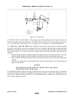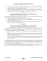
2-65. DRAINING OIL SUMP. To drain the oil sump, provide a suitable container with a minimum capacity of
that required to fill the sump. Remove the engine cowl and on PA-28R-201 airplanes open the oil drain valve
by pushing the center of the drain up and turning counterclockwise. This will hold the drain in the open
position. On PA-28R-201T airplanes remove the oil drain probe from the clip on the right rear engine baffle.
Install suitable hose on probe and insert in quick drain valve located on the underside of the engine. It is
recommended the engine be warmed to operating temperature to insure complete draining of the old oil.
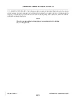
—CAUTION—
When replacing the engine oil quick drain, refer to the Piper Parts Catalog
for the correct part number. Installation of an incorrect drain could damage
the sump or the drain itself. This could lead to loss of engine oil and a
possible engine seizure.
2-66. OIL FILTER (FULL FLOW).
a.
The oil filter should be replaced after each 50 hours of engine operation; this is accomplished by
removing the lockwire from the bolthead at the end of the filter housing, loosening the cartridge, and
removing it from the adapter.
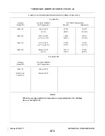
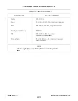
NOTE
Ascertain that oil filter complies with specifications of Continental Aircraft
Engine Service Bulletin M75-7. Warranty effectivity is dependent on the use
of Continental engine parts, per Continental Aircraft Engine Service
Bulletin M75-9.
b. Before discarding the throw away filter, remove the element for inspection by using a Champion cutter
tool, CT-470, available from Champion Spark Plug Co., Toledo, Ohio 43601. It will cut open any spin-
on type oil filter for inspection. Examine the material trapped in the filter for evidence of internal
engine damage, such as chips or particles from bearings. In new or newly overhauled engines, some
small particles of metallic shavings might be found; these are generally of no consequence and should
not be confused with particles produced by impacting, abrasion or pressure. Evidence of internal
engine damage found in the oil filter justifies further examination to determine the cause.
c.
After the filter has been replaced, tighten the new cartridge with 18 to 20 foot-pounds of torque.
Lockwire the bolt head to the loops on the side of the housing, and on Lycoming engines also to the
drilled head of the thermostatic valve. Be sure the lockwire is replaced at both the attached bolthead
and the thermostatic oil cooler bypass. Use MS-20995-C41 safety wire.
Revised: 5/1/80
1B22
*CHEROKEE ARROW III SERVICE MANUAL
HANDLING AND SERVICING
Summary of Contents for ARROW III
Page 4: ...THIS PAGE INTENTIONALLY LEFT BLANK 1A4...
Page 12: ...THIS PAGE INTENTIONALLY LEFT BLANK 1A12...
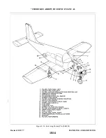
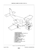
Page 94: ...Figure 4 2 Wing Installation Revised 2 13 89 1D22 CHEROKEE ARROW III SERVICE MANUAL STRUCTURES...
Page 171: ...lH3 INTENTIONALLY LEFT BLANK...
Page 172: ...lH4 INTENTIONALLY LEFT BLANK...
Page 286: ...THIS PAGE INTENTIONALLY LEFT BLANK Revised 2 13 89 2A8...
Page 528: ...INTENTIONALLY LEFT BLANK 2K10 THRU 2L24 2K10...

