c.
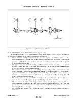
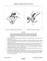
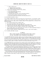
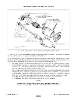
On PA-28R-201, check the position of the pinion to be sure the unit will mesh properly with the
flywheel ring rear. See specifications of unit for correct dimensions. Refer to paragraph 11-63.
11-61. BENCH TESTS.
a.
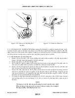
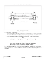
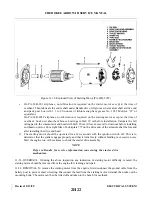
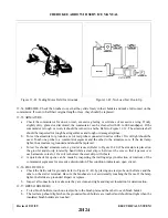
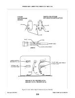
After the starting motor is reassembled, it should be tested to see that the no-load current at a certain
voltage is within specifications as given in paragraph 11-62. To make this test, connect as shown in
Figure 11-42. If current is too high, check the bearing alignment and end play to make sure there is no
binding or interference. Two or three sharp raps on the frame with a rawhide hammer will often help to
align the bearings and free the armature.
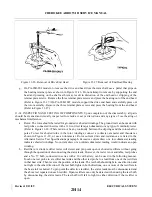
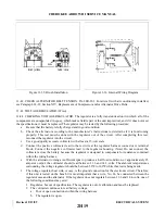
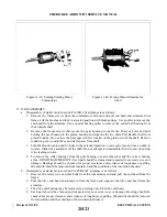
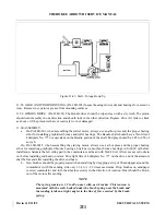
b. If no difficulty is indicated in the above test, a stall torque test may be made to see if the starting motor
is producing its rated cranking power. Make test connections as shown in Figure 11-43.
c.
If torque and current are not within specifications, check the seating of the brushes and internal
connections for high resistance. If these checks are made and found to be in good order, replace frame
and field assembly and retest starter.
11-62. STARTING MOTOR CONTROL CIRCUIT.
a.
Inspect the control circuit wiring between the battery, solenoid and manual starting switches for
breaks, poor connections and faulty insulation. Tighten all connections and make sure solenoid is
firmly mounted and makes a good ground connection.
b. Check the voltage loss across the switch contacts during normal starting. If loss is in excess of 0.2
volts per 100 amperes, the solenoid should be replaced.
c.
If solenoid fails to operate when the manual starting switch is turned on or if it fails to release when
the manual starting switch is released, it should be removed and tested to specifications. If either
opening or closing voltages are not to specifications, replace the solenoid.
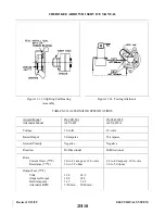
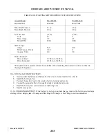
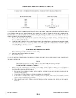
11-63. STA RTING MOTOR SERVICE TEST SPECIFICATIONS. Prestolite specifications for standard
equipment 12-volt starting motors installed on both model aircraft are as shown in Table XI-III.
11-64. BATTERY.
11-65. SERVICING BATTERY. Access to the battery is through the aft side of the baggage compartment. It is
enclosed in a thermoplastic box with a vent system and a drain. The vents allow fresh air to enter the box and
draw off fumes that may accumulate due to the charging process of the battery. The drain is clamped off and
should be opened occasionally to drain any accumulation of liquid or during cleaning of the box. The battery
should be checked for fluid level but must not be filled above the baffle plates. A hydrometer check should be
performed to determine the percent of charge in the battery. All connections must be clean and tight.
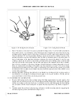
11-66. REMOVAL OF BATTERY.
a.
Remove the access panel to the aft section of the fuselage.
b. Remove battery box cover.
c.
Disconnect the battery cables.
NOTE
Always remove the ground cable first and install last to prevent accidental
short circuiting or arching.
d. Lift the battery from the box.
Revised: 2/13/89
2I2
CHEROKEE ARROW III SERVICE MANUAL
ELECTRICAL SYSTEM
Summary of Contents for ARROW III
Page 4: ...THIS PAGE INTENTIONALLY LEFT BLANK 1A4...
Page 12: ...THIS PAGE INTENTIONALLY LEFT BLANK 1A12...
Page 94: ...Figure 4 2 Wing Installation Revised 2 13 89 1D22 CHEROKEE ARROW III SERVICE MANUAL STRUCTURES...
Page 171: ...lH3 INTENTIONALLY LEFT BLANK...
Page 172: ...lH4 INTENTIONALLY LEFT BLANK...
Page 286: ...THIS PAGE INTENTIONALLY LEFT BLANK Revised 2 13 89 2A8...
Page 528: ...INTENTIONALLY LEFT BLANK 2K10 THRU 2L24 2K10...

