2I14
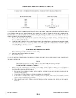
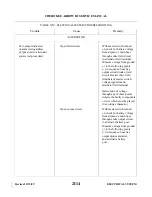
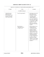
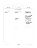
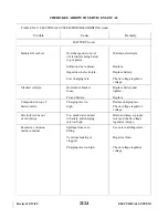
TABLE XI-V. ELECTRICAL SYSTEM TROUBLESHOOTING
Zero output indicated
Open field circuit.
With master switch turned
on ammeter regardless
on, check for battery voltage
of rpm (refer to alternator
from airplane’s main buss
system test procedure).
through entire field circuit
to alternator field terminal.
Measure voltage from ground
(-) to the following points
(+) in sequence: buss bar,
output circuit diodes, field
circuit breaker (SA), field
terminals of master switch,
voltage regulator and
alternator field terminal.
Interruption of voltage
through any of these points
isolates the faulty components
or wire which must be placed.
(See wiring schematic.)
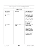
Open output circuit.
With master switch turned
on, check for battery voltage
from airplane’s main buss
through entire output circuit
to alternator battery post.
Measure voltage from ground
(-) to the following points
(+) in sequence: buss bar,
output diodes ammeter,
and alternator battery
post.
Trouble
Cause
Remedy
Revised: 2/13/89
CHEROKEE ARROW III SERVICE MANUAL
ELECTRICAL SYSTEM
ALTERNATOR
Summary of Contents for ARROW III
Page 4: ...THIS PAGE INTENTIONALLY LEFT BLANK 1A4...
Page 12: ...THIS PAGE INTENTIONALLY LEFT BLANK 1A12...
Page 94: ...Figure 4 2 Wing Installation Revised 2 13 89 1D22 CHEROKEE ARROW III SERVICE MANUAL STRUCTURES...
Page 171: ...lH3 INTENTIONALLY LEFT BLANK...
Page 172: ...lH4 INTENTIONALLY LEFT BLANK...
Page 286: ...THIS PAGE INTENTIONALLY LEFT BLANK Revised 2 13 89 2A8...
Page 528: ...INTENTIONALLY LEFT BLANK 2K10 THRU 2L24 2K10...

