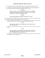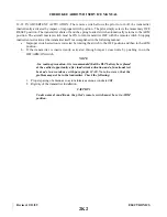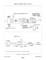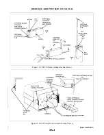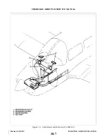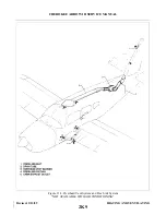
12-8. REMOVAL AND INSTALLATION (NARCO). The ELT is located on the right side of the airplane tail
section ahead of the stabilator.
1. Remove the access panel at fuselage station 228.30.
2. Set the ON/OFF/ARM switch on the transmitter to OFF.
3. Disconnect antenna coaxial cable from ELT.
4. Remove ELT from its mounting bracket by releasing the latch on the strap and sliding the ELT off
the bracket.
5. Extend the portable antenna.
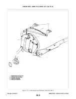
6. Unscrew the four screws that hold the control head to the battery casing and slide apart.
7. Disconnect the battery terminals from the bottom of the circuit board.
8. Discard old battery pack. (DO NOT EXPOSE TO FLAME.)
CAUTION
The battery pack is shipped with a sealant on the inside lip so that a water
tight seal will be retained. DO NOT REMOVE THIS SEALANT.
9. Connect new battery pack terminals to the bottom of the circuit board.
10. Reinsert the control head section into the battery pack being careful not to pinch any wires, and
replace the four screws. If the four holes do not line up, rotate the battery pack 180° and reinsert.
11. Slide the portable antenna back into the stowed position.
12. Place transmitter into its mounting bracket and fasten the strap latch.
13. Connect the antenna coaxial cable to the ELT and ensure that the contact separator is inserted
between the antenna contact finger and the portable antenna.
14. Press RESET button and set ON/OFF/ARM switch to ARM.
15. Make an entry in the aircraft logbook, including the new battery expiration date.
16. A unit operational check may now be performed on the ELT. (Refer to Testing Emergency Locator
Transmitter, paragraph 12-10.)
NOTE
Inspect the external whip antenna for any damage. Avoid bending the whip.
Any sharply bent or kinked whip should be replaced. Antenna damage may
cause structural failure of whip in flight.
Revised: 2/13/89
2J23
CHEROKEE ARROW III SERVICE MANUAL
ELECTRONICS
Summary of Contents for ARROW III
Page 4: ...THIS PAGE INTENTIONALLY LEFT BLANK 1A4...
Page 12: ...THIS PAGE INTENTIONALLY LEFT BLANK 1A12...
Page 94: ...Figure 4 2 Wing Installation Revised 2 13 89 1D22 CHEROKEE ARROW III SERVICE MANUAL STRUCTURES...
Page 171: ...lH3 INTENTIONALLY LEFT BLANK...
Page 172: ...lH4 INTENTIONALLY LEFT BLANK...
Page 286: ...THIS PAGE INTENTIONALLY LEFT BLANK Revised 2 13 89 2A8...
Page 528: ...INTENTIONALLY LEFT BLANK 2K10 THRU 2L24 2K10...

