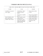
2. When working in the tail cone of the aircraft, attach a tail stand to the tail.
3. With immediate area clear of flammables (grease, hydraulic fluid, fuel) and with the oxygen system
OFF, connect the mask or tube to an outlet to exhaust any pressure in the system.
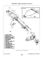
4. Remove the screws and loosen clamps securing the shroud and disconnect the tube.
5. Remove the spring clamps securing vent tube to cylinder shroud and disconnect the tube.
6. Carefully separate the shroud along the high pressure lines.
7. The high pressure fitting on the regulator-control valve incorporates a valve that opens only when a
line is connected to it. With this in mind, carefully unscrew the high pressure line until the pressure
decreases, then remove the line. Disconnect low pressure lines as well.
8. Loosen and open the clamps securing the bottle to the shelf. Carefully move the bottle in such a way
that fair access can be made to the control mechanism.
CAUTION
Be extremely careful not to kink the cable.
9. Disconnect the control cable.
10. Remove tank from the aircraft being careful not to damage the regulator-control valve.
14-64. REMOVAL OF RECHARGE VALVE. The recharge valve is located on the left rear side of the aircraft
and is covered by its own access door. The valve is interconnected with the gauge line as well as the regulator
control valve and is constantly under cylinder pressure as long as the high pressure line is attached to the
regulator.
NOTE
The recommended service life for the recharge valve is 5 years and the
oxygen cylinder must be hydrostatically tested every 5 years. It is
recommended that the recharge valve be removed and replaced when the
cylinder is removed for services.
1. Due to the location of the recharge valve, it is necessary to remove the oxygen cylinder. For ease of
removal, it is recommended that the cylinder shelf also be removed.
2. Remove screws that secure the recharge valve’s protective shroud to valve mounting dish and slide
shroud back over high pressure line.
3. Unscrew high pressure line fitting from recharge valve and with somebody turning the screw from
outside the aircraft, back-up the nut to remove valve.
14-65. INSTALLATION OF RECHARGE VALVE.
1. Insert valve through opening in mounting cap and align bolt holes.
2. With safety chain and information plate mounting washer aligned at one of the holes, install mounting
bolts.
3. Apply Teflon tape to male threads per instructions, Section 14-60.
4. Connect high pressure line to valve and tighten fitting to a torque of 30 to 50 inch-pounds.
5. Install valve protective shroud.
Revised: 2/13/89
3C10
CHEROKEE ARROW III SERVICE MANUAL
ACCESSORIES AND UTILITIES
Summary of Contents for ARROW III
Page 4: ...THIS PAGE INTENTIONALLY LEFT BLANK 1A4...
Page 12: ...THIS PAGE INTENTIONALLY LEFT BLANK 1A12...
Page 94: ...Figure 4 2 Wing Installation Revised 2 13 89 1D22 CHEROKEE ARROW III SERVICE MANUAL STRUCTURES...
Page 171: ...lH3 INTENTIONALLY LEFT BLANK...
Page 172: ...lH4 INTENTIONALLY LEFT BLANK...
Page 286: ...THIS PAGE INTENTIONALLY LEFT BLANK Revised 2 13 89 2A8...
Page 528: ...INTENTIONALLY LEFT BLANK 2K10 THRU 2L24 2K10...

