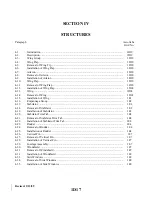
SECTION IV
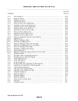
STRUCTURES
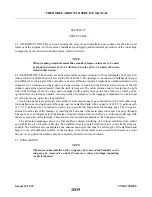
4-l. INTRODUCTION. This section explains the removal and installation procedures for the structural
surfaces of the airplane. For the removal, installation, and rigging and adjustment procedures of the controlling
components of the various structural surfaces, refer to Section V.
NOTE
When torquing structural assemblies, standard torque values are to be used
as found in Section II or FAA Advisory Circular 43.13-1A, unless otherwise
stated in this section.
4-2. DESCRIPTION. The aircrafts are all metal semi-monocoque structure with overall lengths of 24 feet 8.16
inches for the PA-28R-201 and 25 feet for the PA-28R-201T. The fuselage is constructed of bulkheads, stringer
and stiffeners, to which all of the outer skin is riveted. Windows include a single pane windshield and six side
windows. A11 windows are single pane. A storm window is located in the forward lower section of the left
window and can be opened inward when the latch is released. The cabin entrance door is located on the right
side of the fuselage, above the wing, and is equipped with a safety latch on the top of the door, which can be
operated from the inside or outside. A door provided for entrance to the baggage compartment is located just
aft of the right wing with a key lock installed.
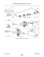
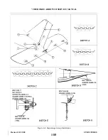
Each wing panel is an all metal, full cantilever semi-monocoque type construction with a removable wing
tip. Installed in each wing ahead of the main spar is a metal fuel tank with a capacity of 38.5 U.S. gallons each
or 77 U.S. gallons total. Attached to each wing is an aileron, flap and main landing gear. The wings are
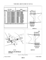
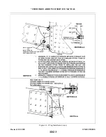
attached to each side of the fuselage by inserting the butt ends of the main spars into a spar box carry-through.
The spar box is an integral part of the fuselage structure which provides, in effect, a continuous main spar with
splices at each side of the fuselage. There are also fore and aft attachments at the front and rear spars.
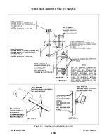
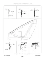
The all metal empennage group is a full cantilever design consisting of a vertical stabilizer (fin), rudder
and stabilator, all with removable tips. The stabilator has a trim tab attached that is controllable from the
cockpit. The stabilator also incorporates one channel main spar that runs the full length of the stabilator and
hinges to the aft bulkhead assembly of the fuselage. All exterior surfaces are coated with enamel or acrylic
lacquer. As an option the airplane may be completely primed with zinc chromate.
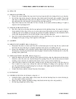
4-3. WING GROUP.
NOTE
The major subassemblies of the wing may be removed individually or the
wing may be removed as a unit. To remove a wing, a fuselage supporting
cradle is required.
Issued: 12/15/76
1D19
* CHEROKEE ARROW III SERVICE MANUAL
STRUCTURES
Summary of Contents for ARROW III
Page 4: ...THIS PAGE INTENTIONALLY LEFT BLANK 1A4...
Page 12: ...THIS PAGE INTENTIONALLY LEFT BLANK 1A12...
Page 94: ...Figure 4 2 Wing Installation Revised 2 13 89 1D22 CHEROKEE ARROW III SERVICE MANUAL STRUCTURES...
Page 171: ...lH3 INTENTIONALLY LEFT BLANK...
Page 172: ...lH4 INTENTIONALLY LEFT BLANK...
Page 286: ...THIS PAGE INTENTIONALLY LEFT BLANK Revised 2 13 89 2A8...
Page 528: ...INTENTIONALLY LEFT BLANK 2K10 THRU 2L24 2K10...

