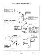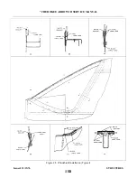
4-4. WING TIP.
4-5. REMOVAL OF WING TIP.
a.
Remove the screws holding the wing tip to the wing, being careful not to damage the wing or wing tip.
b. Pull off the wing tip far enough to disconnect the position and strobe light wire assembly. The ground
lead may be disconnected at the point of connection on the wing rib, and the positive lead may be
disconnected at the wire terminal or unscrewed from the light assembly.
c.
Inspect the wing tip to ascertain that it is free of cracks, severe nicks and minor damage. If repair is
required, refer to paragraph 4-56.
4-6. INSTALLATION OF WING TIP.
a.
Place the wing tip in a position that the navigation and strobe light leads may be connected. Connect
the ground lead to the wing rib by use of a screw and nut, and the positive lead to the position light by
connecting the wire terminals or screwing the connectors together. Insulate the wire terminals and be
certain that the ground lead is free of dirt and film to insure a good connection.
b. Insert the wing tip into position and install the screws around the tip. Use caution to refrain from
damaging the wing tip or wing. Check operation of the lights.
4-7. AILERON.
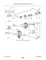
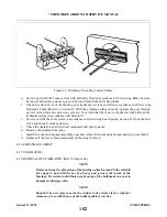
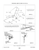
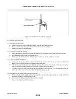
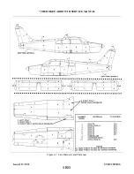
4-8. REMOVAL OF AILERON. (Refer to Figure 4-1.)
a.
Disconnect the aileron control rod at the aileron attachment point by removing the nut, washers and
bolt from the rod end bearing. To simplify installation note location of washers removed.
b. Remove the attaching screws, with nuts, from the hinges at the leading edge of the aileron, and remove
the aileron by lowering the inboard end and swinging it forward to allow the balance arm to clear the
opening in the outboard rib.
4-9. INSTALLATION OF AILERON. (Refer to Figure 4-1.)
a.
Install the balance arm into the opening in the outboard rib by moving the inboard end of the aileron
forward to allow the arm to be inserted through the opening. Move the aileron into place and install
attaching screws and nuts. Ascertain that the aileron is free to move with no interference.
b. Attach the aileron control rod with bolts, washers and nut, dividing the washers so that the aileron is
free to rotate from stop to stop without the control rod binding or rubbing on the opening in the aft
spar. Be certain that the rod end bearing has no side play when tightening the bolt and that the rod does
not contact the side of the bracket.
c.
Actuate the aileron controls to insure freedom of movement.
4-10. WING FLAP.
4-11. REMOVAL OF WING FLAP. (Refer to Figure 4-1.)
a.
Extend the flaps to their fullest degree and remove the bolt and bushing from the rod end bearing by
use of an angle or offset screwdriver.
b. Remove the nuts, washers, bushing and hinge bolts that hold the flap to the wing assembly.
c.
Pull the flap straight back off the wing.
Issued: 12/15/76
1D20
* CHEROKEE ARROW III SERVICE MANUAL
STRUCTURES
Summary of Contents for ARROW III
Page 4: ...THIS PAGE INTENTIONALLY LEFT BLANK 1A4...
Page 12: ...THIS PAGE INTENTIONALLY LEFT BLANK 1A12...
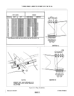
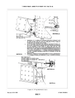
Page 94: ...Figure 4 2 Wing Installation Revised 2 13 89 1D22 CHEROKEE ARROW III SERVICE MANUAL STRUCTURES...
Page 171: ...lH3 INTENTIONALLY LEFT BLANK...
Page 172: ...lH4 INTENTIONALLY LEFT BLANK...
Page 286: ...THIS PAGE INTENTIONALLY LEFT BLANK Revised 2 13 89 2A8...
Page 528: ...INTENTIONALLY LEFT BLANK 2K10 THRU 2L24 2K10...

