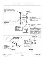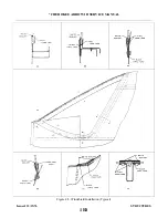
4-64. CONTROL SURFACE BALANCING.
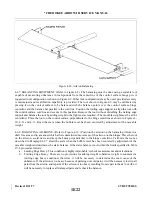
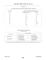
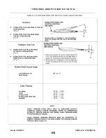
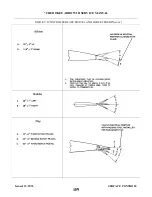
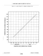
4-65. CHECKING CONTROL SURFACE BALANCE. The movable control surfaces have been statically
balanced at the time of installation at the factory and normally should not require rebalancing. Where possible
the control surfaces where set with the balance weight on the heavy side of the limits, to permit limited repair
or paint touch-up without adjusting the balance weight. It should be noted however, that spar control surfaces
are delivered unpainted and the static balance will not necessarily fall within the limits provided, this is more
pronounced on the stabilators and rudders. The completed control surface, including paint, should be within
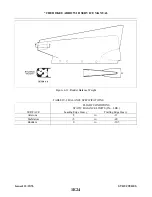
the limits given in Table IV-I. If the surface is not to be painted, the balance weight will probably require
adjustment. All replacement control surfaces, or surfaces that have been repainted or repaired, should be
rebalanced according to the procedures given in Paragraphs 4-65 thru 4-70. The static balance of the surfaces
must be as specified in Table IV-I.
Before balancing any control surface, it must be complete including tip, trim/servo tabs and tab actuating
arms or push rods with bearings as applicable, and all optional equipment which is mounted on or in the
control surface when it is flown, including paint, position lights and wiring, static wicks, scuff boots, etc.
If optional equipment is added or removed after balancing, the control surface must be rebalanced. During
balancing, trim/servo tabs must be maintained in their neutral positions.
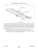
4-66. CHECKING CONTROL SURFACES FREE PLAY. The following checks are recommended before
balancing to ascertain the amount of “free play” in the stabilator, stabilator trim tab and aileron:
a.
Stabilator: Check the stabilator for any “free play” at its attachment points by grasping each half near
the tip and gently trying to move it up and down, fore and aft, and in and out. No play is allowed.
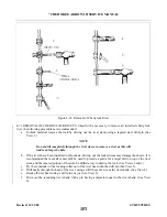
b. Stabilator Trim Tab: Set the stabilator trim tab in neutral position. This neutral position is determined
with the airplane properly rigged per instructions given in Section V of this Service Manual and the
trim indicator at its neutral position. Obtain a straightedge long enough to extend from the ground up
to a few inches above the trim tab trailing edge. Place the straightedge next to the trim tab inboard
(center) trailing edge, secure the stabilator in neutral and grasping the tab, gently move it up and down,
mark the limit of tab free play on the straightedge. The overall travel (free play) must not exceed 0.15
of an inch. The use of a dial indicator and fixed stand in recommended.
c.
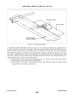
Aileron: Set the aileron in its neutral position and secure. Obtain a straightedge long enough to extend
from the ground up to a few inches above the ai1eron trailing edge. Place the straightedge next to the
aileron trailing edge and gently move the aileron up and down, mark the limit of travel (free play) on
the straightedge. The overall travel (free play) must not exceed 0.24 of an inch. Should free play
exceed the limit stated make necessary repairs as required to eliminate excessive free play.
Revised: 8/31/77
1E20
* CHEROKEE ARROW III SERVICE MANUAL
STRUCTURES
Summary of Contents for ARROW III
Page 4: ...THIS PAGE INTENTIONALLY LEFT BLANK 1A4...
Page 12: ...THIS PAGE INTENTIONALLY LEFT BLANK 1A12...
Page 94: ...Figure 4 2 Wing Installation Revised 2 13 89 1D22 CHEROKEE ARROW III SERVICE MANUAL STRUCTURES...
Page 171: ...lH3 INTENTIONALLY LEFT BLANK...
Page 172: ...lH4 INTENTIONALLY LEFT BLANK...
Page 286: ...THIS PAGE INTENTIONALLY LEFT BLANK Revised 2 13 89 2A8...
Page 528: ...INTENTIONALLY LEFT BLANK 2K10 THRU 2L24 2K10...

