SECTION V
SURFACE CONTROLS
5-1. INTRODUCTION. This section contains the explanation for the removal, installation, rigging and
adjustment procedures for the control assemblies of the various structural surfaces. For the removal and
installation of the structural surfaces of the airplane, refer to Section IV. The assemblies need not be removed
in order of paragraphs since each paragraph describes the individual removal and installation of the
component.
5-2. DESCRIPTION. The airplane is controlled in flight by the use of three standard primary control surfaces,
consisting of the ailerons, stabilator and rudder. Operation of these controls is through the movement of the
dual control columns and dual rudder pedals. The individual surfaces are connected to their control
components through the use of cables and push-pull tubes. Provision for directional and longitudinal trim
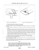
control is provided by an adjustable trim mechanism for the rudder and stabilator. The flaps are mechanically
operated and can be positioned in four locations of 0, 10, 25 and 40 degrees.
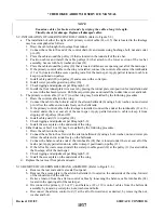
The aileron controls consist of two-control wheels connected by torque tubes to sprockets on each end of
the horizontal control column. A chain is wrapped around the sprockets and around a double sprocket on the
vertical post of the control column. The chain is connected to the primary aileron control cable which is routed
through the center of the fuselage to the main spar and out through the wings to a bellcrank in each wing. A
balance cable is also connected to the bellcrank. As the control wheels are moved, the control cables move the
bellcranks and actuate push-pull rods to move the ailerons.
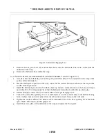
The stabilator controls are also connected to the control column. From the connecting point, cables are
routed around a series of pulleys down under the floor and aft to the tail section of the airplane. The aft end of
the cables connect to the stabilator balance arm which in turn is connected to the stabilator. When the control
wheels are moved forward or aft, the cables move the balance arm up and down rotating the stabilator on its
hinge points.
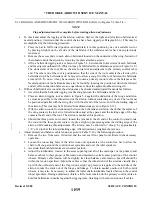
The rudder is controlled by the pilot’s and co-pilot’s rudder pedals. Cables are connected to both sides of
the rudder pedal assembly and are routed aft through the bottom of the fuselage to the rudder horn. When one
rudder pedal is pushed, the cables move in opposite directions turning the rudder horn and rudder. The wing
flap system is operated by a lever located between the front seats.
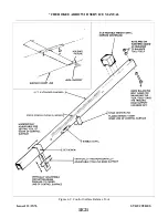
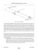
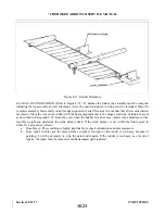
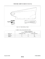
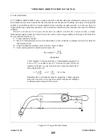
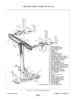
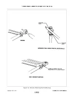
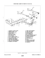
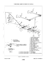
For a visual description of the various control systems, refer to the illustrated figures throughout this
section.
5-3. STANDARD PROCEDURES. The following tips may be helpful in the removal, installation and rigging
of the various assemblies:
a.
It is recommended, though not always necessary to level and place the airplane on jacks during rigging
and adjustment.
b. Remove turnbuckle barrels from cable ends before withdrawing the cables through the structures.
c.
Tie a cord to the cable end before withdrawing the cable through the structures to facilitate
reinstallation of cable.
d. Turnbuckle stations are given at their neutral positions.
e.
When referring to marking cable end, etc., before disconnecting a felt marking pen may be used.
f.
Assemble and adjust the turnbuckles so that each terminal is screwed an approximately equal distance
into the barrel. Do not turn the terminals in such a manner that will put a permanent “twist” into the
cables.
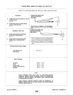
g. Cable tensions should be taken with the appropriate control surface in its neutral position.
Issued: 12/15/76
1F7
* CHEROKEE ARROW III SERVICE MANUAL
SURFACE CONTROLS
Summary of Contents for ARROW III
Page 4: ...THIS PAGE INTENTIONALLY LEFT BLANK 1A4...
Page 12: ...THIS PAGE INTENTIONALLY LEFT BLANK 1A12...
Page 94: ...Figure 4 2 Wing Installation Revised 2 13 89 1D22 CHEROKEE ARROW III SERVICE MANUAL STRUCTURES...
Page 171: ...lH3 INTENTIONALLY LEFT BLANK...
Page 172: ...lH4 INTENTIONALLY LEFT BLANK...
Page 286: ...THIS PAGE INTENTIONALLY LEFT BLANK Revised 2 13 89 2A8...
Page 528: ...INTENTIONALLY LEFT BLANK 2K10 THRU 2L24 2K10...

