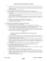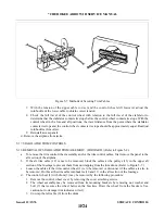
5-7. AILERON CONTROLS.
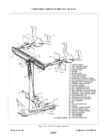
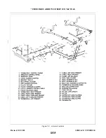
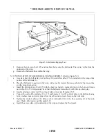
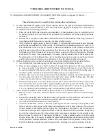
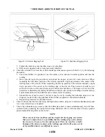
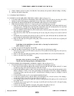
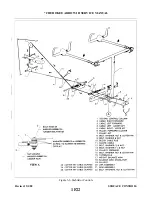
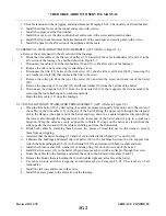
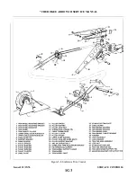
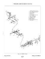
5-8. REMOVAL OF AILERON CONTROL CABLES. (Refer to Figure 5-2.)
a.
For the removal of either the control cables in the fuselage or the wings, first remove the rear seat floor
panel.
following procedure may be used:
1. Remove the two front seats from the airplane.
2. Remove the tunnel cover located aft of the tee bar assembly by removing the rudder trim control
knob and trim cover attaching screws. Roll back the carpet from the tunnel and remove the tunnel
plate that is located just aft of the tee bar assembly by removing the plate attaching screws.
NOTE
To help facilitate reinstallation of control cables, mark the cable ends and
attach a line where applicable before drawing them through the fuselage or
wing.
3. Separate the primary control cable (14 or 15) at the turnbuckle (12 or 16) located under
the rear seat or floor panel aft of the main spar.
4. Remove the cable pulleys (8) attached to the lower-section of the control column tee bar assembly
by removing the pulley attaching bolt (21).
5. Move the cable guard (20) under the pulley cluster (9) located just aft of the lower portion of the
tee bar by removing the cotter pin from the exposed end of the guard and sliding it to the left or
right as required.
6. Remove the cotter pins used as cable guards at the pulley (10) in the forward area of the floor
opening aft of the main spar.
7. Disconnect the cable (14 or 15) from the control chain (4) at the control column tee bar assembly
by removing the cotter pin, nut, bolt and bushing (23) that connect the two together. Secure the
chains in some manner to prevent them from unwrapping from around the sprockets.
8. Draw the cable back through the floor tunnel.
c.
The primary control cable (13 or 17) in either wing may be removed by the following procedure:
1. Remove the access plate to the aileron bellcrank (6) located on the underside of the wing forward
of the inboard end of the aileron.
2. If not previously disconnected, separate the cable at the turnbuckle (12 or 16) located in the area
aft of the main spar.
3. Disconnect the cable from the forward end of the aileron bellcrank by removing the cotter pin, nut,
washer and bolt.
4. Remove cable guard from pulley (28).
5. Draw the cable from the wing.
d. Either balance cable (18 or 19) may be removed by the following procedure:
1. Separate the balance cable at the turnbuckle (24) in the right side of the opening aft of the main
spar.
2. If the left balance cable is to be removed, remove the cotter pin used as a cable guard at the pulley
(11) in the center of the opening.
3. Remove the access plate to the aileron bellcrank (6) located on the underside of the wing forward
of the inboard end of the aileron.
4. Disconnect the cable from the aft end of the aileron bellcrank by removing the cotter pin, nut,
washer and bolt.
5. Draw the cable from the wing.
Issued: 12/15/76
1F16
* CHEROKEE ARROW III SERVICE MANUAL
SURFACE CONTROLS
Summary of Contents for ARROW III
Page 4: ...THIS PAGE INTENTIONALLY LEFT BLANK 1A4...
Page 12: ...THIS PAGE INTENTIONALLY LEFT BLANK 1A12...
Page 94: ...Figure 4 2 Wing Installation Revised 2 13 89 1D22 CHEROKEE ARROW III SERVICE MANUAL STRUCTURES...
Page 171: ...lH3 INTENTIONALLY LEFT BLANK...
Page 172: ...lH4 INTENTIONALLY LEFT BLANK...
Page 286: ...THIS PAGE INTENTIONALLY LEFT BLANK Revised 2 13 89 2A8...
Page 528: ...INTENTIONALLY LEFT BLANK 2K10 THRU 2L24 2K10...

