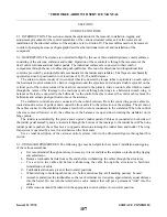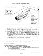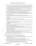
g . Check complete system for safety of turnbuckle, bolts, and smooth operation without binding or chafing.
h . Install access plates and panels.
5-13. STA B I L ATOR CONTROLS.
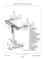
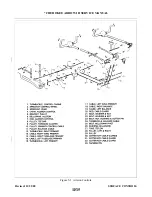
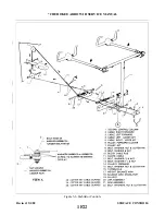
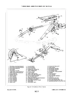
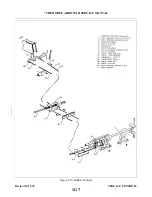
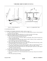
5-14. REMOVAL OF STA B I L ATOR CONTROL CABLES. (Refer to Figure 5-6.)
a .
To remove either the forward or aft stabilator cables, first remove the access panel to the aft section of the
fuselage located in the baggage compartment, the two front seats, and the rear seats floor panel.
b .
Disconnect the desired control cable at the turnbuckle in the aft section of the fuselage.
c .
Either forward stabilator cable (2 or 3) may be removed by the following procedure:
1 .
Remove the tunnel carpet and cover plate by removing the rudder trim control knob and trim cover
attaching screws. Roll back the carpet from the tunnel and remove the tunnel plate that is located just
aft of the tee bar assembly by removing the plate attaching screws.
the forward area of the tunnel.
3 .
4 .
Within the access opening aft of the main spar, remove the cable rub blocks that are attached to the
spar housing be removing the block attaching screws.
5 . Remove the cotter pin cable guard at the pulley cluster located in the aft area the access opening aft
of the main spar.
N O T E
To facilitate in the installation of control cables, a line may be attached to the
cable end prior to removal.
6 .
Draw the cables aft through the floor tunnel.
d . Either aft stabilator control cable (4 or 5) may be removed by the following procedure:
1 . Disconnect the cable end at the balance arm (18) of the stabilator by removing the cotter pin, nut,
2 . Remove the cotter pin cable guard at the pulley (7) located either above or below the balance arm.
3 . Remove the cable from the airplane.
N O T E
Examine cables for broken strands by wiping the cable along its length.
Visually check for damage. Replace all damaged cables.
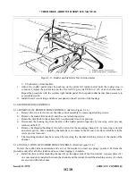
5-15. INSTA L L ATION OF STA B I L ATOR CONTROL CABLES. (Refer to Figure 5-6.)
a .
The forward stabilator cables (2 and 3) may be installed by the following procedure:
1 . Draw the control cable through the floor tunnel. Ascertain that the right (upper) cable (2) is routed
around the pulleys (14) in the forward area of the floor tunnel.
3 . If the aft control cable (4 or 5) is not installed, install per Step b.
4 . Connect the control cable to the aft cable at the turnbuckle (16) in the aft section of the fuselage.
Apply partial tension to cable to keep it positioned on pulleys.
5 .
For the right control cable (2), install the cotter pin cable guards at the pulley(s) (14) in the forward
area of the tunnel.
6 .
Within the access opening aft of the main spar, install the cable run blocks (10) to the spar housing
and secure with screws.
7 . In the access opening, install the cotter pin cable guard at the pulley cluster (6).
8 .
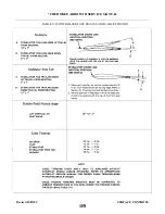
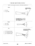
Set the tension and check rigging and adjustment per Paragraph 5-16.
Revised: 2/13/89
1F21
* CHEROKEE ARROW III SERVICE MANUAL
SURFACE CONTROLS
Summary of Contents for ARROW III
Page 4: ...THIS PAGE INTENTIONALLY LEFT BLANK 1A4...
Page 12: ...THIS PAGE INTENTIONALLY LEFT BLANK 1A12...
Page 94: ...Figure 4 2 Wing Installation Revised 2 13 89 1D22 CHEROKEE ARROW III SERVICE MANUAL STRUCTURES...
Page 171: ...lH3 INTENTIONALLY LEFT BLANK...
Page 172: ...lH4 INTENTIONALLY LEFT BLANK...
Page 286: ...THIS PAGE INTENTIONALLY LEFT BLANK Revised 2 13 89 2A8...
Page 528: ...INTENTIONALLY LEFT BLANK 2K10 THRU 2L24 2K10...

