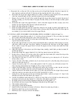
9. Install the floor tunnel plate and trim covers by placing the tunnel plate into position for
installation and secure with the attaching screws. Roll the carpet into place and install the rudder
trim cover and knob.
10. Install the front seats and rear seat floor panel.
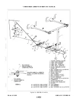
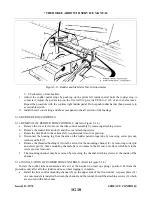
b. Either aft stabilator control cable (4 or 5) may be installed by the following procedure:
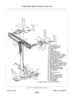
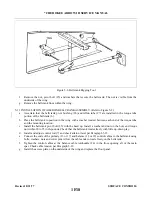
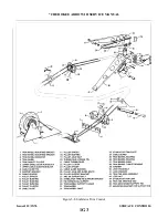
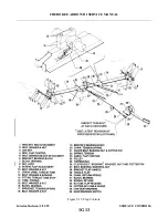
1. Route the cable (4 or 5) around its pulley (7) located either over or under the balance arm (18) of
the stabilator.
(Insure bushing is installed with bolt.)
4. Install the cotter pin cable guard at the pulley (7), where required.
5. Set cable tension and check rigging and adjustment per Paragraph 5-17.
6. Install the seats and access panels.
5-16. RIGGING AND ADJUSTMENT OF STABILATOR CONTROLS.
a.
Level the airplane. (Refer to Leveling, Section II.)
b. To check and set the correct degree of stabilator travel, the following procedure may be used:
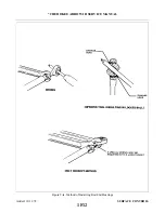
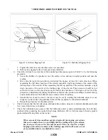
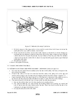
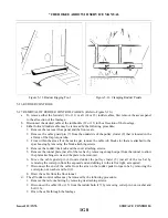
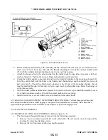
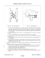
1. Check the stabilator travel by placing a rigging tool on the upper surface of the stabilator as shown
in Figure 5-5 (This tool may be fabricated from dimensions given in Figure 5-20.)
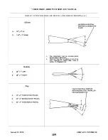
2. Set on a bubble protractor the number of degree up travel as given in Table V-I and place it on the
rigging tool. Raise the trailing edge of the stabilator and determine that when the stabilator
contacts its stops, the bubble of the protractor is centered.
NOTE
The stabilator should contact both of its stops before the control wheel
contacts its stops.
3. Set on the protractor the number of degrees down travel as given in-Table V-I and again place it on
the rigging tool. Lower the trailing edge of the stabilator and determine that when it contacts its
stops, the bubble of the protractor is centered.
4. Should the stabilator travel be incorrect in either the up or down position, remove the tail cone
fairing by removing the attaching screws and with the use of the rigging tool and bubble protractor
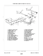
turn the stops located at each stabilator hinge in or out (Refer to Figure 5-13.) to obtain the correct
degree of travel.
5. Ascertain that the lock nuts of the stop screws are secure and reinstall the tail cone fairing.
c.
To check and set stabilator control cable tension, the following procedure may be used:
1. Ascertain that the stabilator travel is correct.
2. Remove the access panel to the aft section of the fuselage.
3. Secure the control column in the near forward position. Allow 1/4 + 1/32 inch between the column
aft the stop bumper.
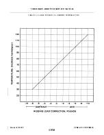
4. Check each control cable for the correct tension as given in Table V-I.
5. Should tension be incorrect, loosen the turnbuckle of the lower cable in the aft section of the
fuselage and adjust the turnbuckle of the upper cable to obtain correct tension. Cable tension
should be obtained with the control wheel at the 1/4 + 1/32 inch dimension from the stop and the
stabilator contacting its stop.
6. Check safety of all turnbuckles and bolts.
Revised: 5/1/80
1F23
* CHEROKEE ARROW III SERVICE MANUAL
SURFACE CONTROLS
Summary of Contents for ARROW III
Page 4: ...THIS PAGE INTENTIONALLY LEFT BLANK 1A4...
Page 12: ...THIS PAGE INTENTIONALLY LEFT BLANK 1A12...
Page 94: ...Figure 4 2 Wing Installation Revised 2 13 89 1D22 CHEROKEE ARROW III SERVICE MANUAL STRUCTURES...
Page 171: ...lH3 INTENTIONALLY LEFT BLANK...
Page 172: ...lH4 INTENTIONALLY LEFT BLANK...
Page 286: ...THIS PAGE INTENTIONALLY LEFT BLANK Revised 2 13 89 2A8...
Page 528: ...INTENTIONALLY LEFT BLANK 2K10 THRU 2L24 2K10...

