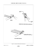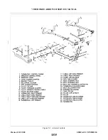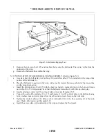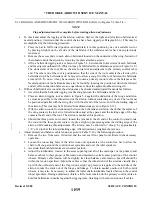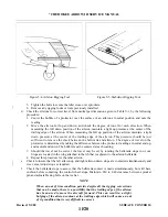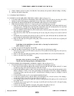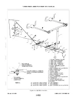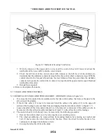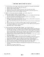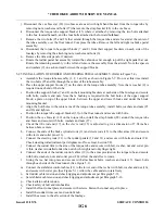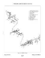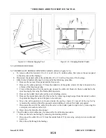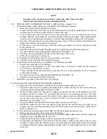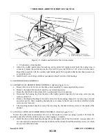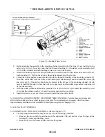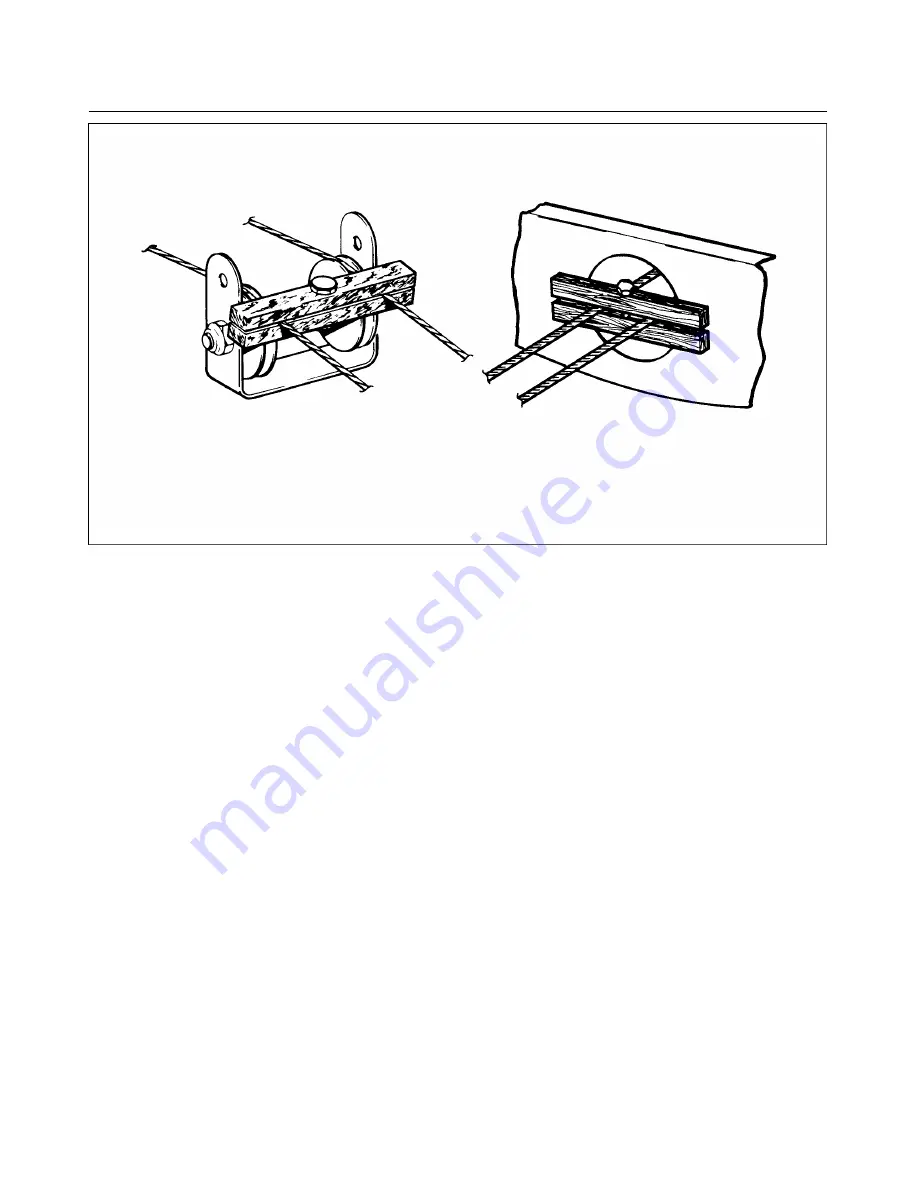
Figure 5-7. Methods of Securing Trim Cables
7. With the tension of the upper cable correct and the control wheel still forward, adjust the
turnbuckle of the lower cable to obtain correct tension.
8. Check the full travel of the control wheel with relation to the full travel of the stabilator to
determine that the stabilator contacts its stops before the control wheel contacts its stops. With the
control wheel in the fore and aft positions, the travel distance from the point where the stabilator
contacts its stops and the control wheel contacts its stops should be approximately equal. Readjust
turnbuckles if incorrect.
9. Reinstall access panels.
d. Remove the airplane from jacks.
5-17. STABILATOR TRIM CONTROLS.
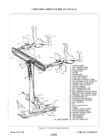
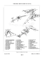
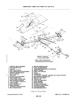
5-18. REMOVAL OF STABILATOR TRIM ASSEMBLY. (FORWARD.) (Refer to Figure 5-8.)
a.
To remove the trim control wheel assembly and/or the trim control cables, first remove the panel to the
aft section of the airplane.
section of the fuselage to prevent them from unwrapping from the trim drum. (Refer to Figure 5-7.)
c.
d. The control wheel (1) with drum (3) may be removed by the following procedure:
1. Remove the control wheel cover by removing the cover attaching screws.
2. The wheel assembly may be removed from its mounting brackets by removing nut, washer and
3. Unwrap the left cable (9) from the drum.
Issued: 12/15/76
1F24
* CHEROKEE ARROW III SERVICE MANUAL
SURFACE CONTROLS
Summary of Contents for ARROW III
Page 4: ...THIS PAGE INTENTIONALLY LEFT BLANK 1A4...
Page 12: ...THIS PAGE INTENTIONALLY LEFT BLANK 1A12...
Page 94: ...Figure 4 2 Wing Installation Revised 2 13 89 1D22 CHEROKEE ARROW III SERVICE MANUAL STRUCTURES...
Page 171: ...lH3 INTENTIONALLY LEFT BLANK...
Page 172: ...lH4 INTENTIONALLY LEFT BLANK...
Page 286: ...THIS PAGE INTENTIONALLY LEFT BLANK Revised 2 13 89 2A8...
Page 528: ...INTENTIONALLY LEFT BLANK 2K10 THRU 2L24 2K10...

