N O T E
Examine cables for broken strands by wiping the cable along its length.
Visually check for damage. Replace all damaged cables.
5 - 2 8 .
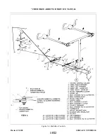
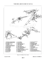
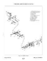
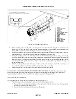
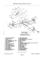
I N S TA L L ATION OF RUDDER CONTROL CABLES. (Refer to Figure 5-10.)
a .
The forward rudder control cables may be installed by the following procedure:
1 .
Draw the control cable through the floor tunnel.
2 . Connect the end of the cable to the arm on the rudder pedal torque tube by installing bolt, washer, nut
and cotter pin (2). Allow the cable end free to rotate on the arm.
3 .
Connect the cable to the aft control cable at the turnbuckle (12 or 13) in the aft section of the
fuselage. If the aft control cables are not installed, install at this time per Step b. Apply partial tension
to cable to keep it positioned on the pulleys. Ascertain that each cable is in the groove of its pulley.
of the tunnel and secure the guard with cotter pin.
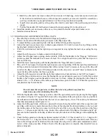
5 . Within the area aft of the main spar, install the cable guard blocks (6) onto the spar housing and
secure with screws.
6 .
Install the cable guard (7) under the pulley cluster (9) located just aft of the flap torque tube.
7 . Set cable tension and check rigging and adjustment per Paragraph 5-29.
8 .
Install the forward tunnel plate aft of the tee bar and secure with screws.
9 .
Put the floor carpet in place and secure.
1 0 . Install the lower and upper selector covers and secure with screws.
11 . Install the rear seat floor panel and install front seats.
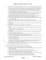
b . The aft rudder control cables may be installed by the following procedure:
1 . Position the control cable in the fuselage.
2 .
3 .
Connect the other cable end to forward control cable (10 or 11) at the turnbuckle (12 or 13) in the aft
section of the fuselage.
4 . Set cable tension and check rigging and adjustment per Paragraph 5-29.
5 .
Install tail cone fairing and secure with screws.
c .
Install the access panel to the aft section of the fuselage.
5-29. RIGGING AND ADJUSTMENT OF RUDDER CONTROLS.
a .
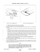
To check and set the correct degree of rudder travel, the following procedure may be used:
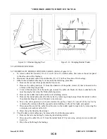
1 . Check the rudder travel by swinging the rudder until it contacts its stops. If the control cables are
connected, use the rudder pedals to swing the rudder.
2 .
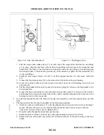
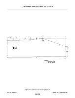
With the rudder against its stop, place a rigging tool against the side of the rudder and vertical
stabilizer as shown in Figure 5-11. (Ascertain that the tool is not contacting any rivets.) If no gap
exists between the rigging tool and the surface of the rudder and vertical stabilizer, the rudder stop
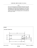
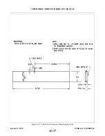
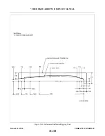
for one direction of travel is correct as required in Table V-I. (This tool may be fabricated from
dimensions given in Figure 5-13.)
3 .
Swing the rudder in the other direction and check travel as directed in Step 2.
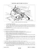
4 . Should the rudder travel be incorrect showing a gap between the tool and any part of the control
surfaces, the tail cone fairing should be removed and the stops reset to obtain correct rudder travel.
(Refer to Figure 5-13.)
b .
To set cable tension and alignment of the rudder, the following procedure may be used:
1 .
Remove the access panel to the aft section of the fuselage.
2 . Ascertain that the nose gear steering has been aligned and rudder pedals set fore and aft according to
Alignment of Nose Landing Gear Section VII.
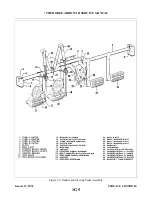
3 . Clamp the rudder pedals to align in a lateral position as shown in Figure 5-12.
4 . Evenly adjust the turnbuckle in the aft section of the fuselage to obtain proper cable tension as given
in Table V-I and to allow the rudder to align at neutral position. Neutral position can be determined
by standing behind the airplane and sighting the rudder with the vertical stabilizer or the center of the
trim screw.
Revised: 2/13/89
1G9
* CHEROKEE ARROW III SERVICE MANUAL
SURFACE CONTROLS
Summary of Contents for ARROW III
Page 4: ...THIS PAGE INTENTIONALLY LEFT BLANK 1A4...
Page 12: ...THIS PAGE INTENTIONALLY LEFT BLANK 1A12...
Page 94: ...Figure 4 2 Wing Installation Revised 2 13 89 1D22 CHEROKEE ARROW III SERVICE MANUAL STRUCTURES...
Page 171: ...lH3 INTENTIONALLY LEFT BLANK...
Page 172: ...lH4 INTENTIONALLY LEFT BLANK...
Page 286: ...THIS PAGE INTENTIONALLY LEFT BLANK Revised 2 13 89 2A8...
Page 528: ...INTENTIONALLY LEFT BLANK 2K10 THRU 2L24 2K10...

