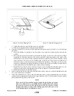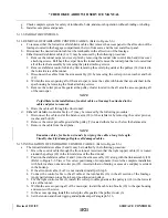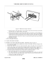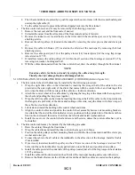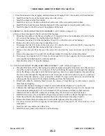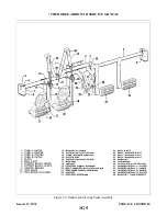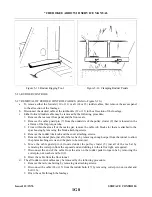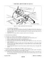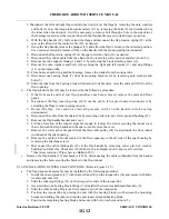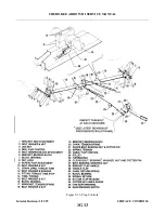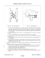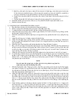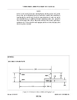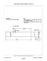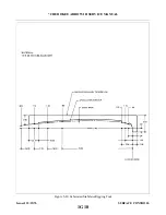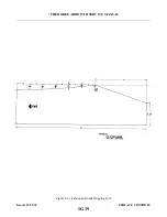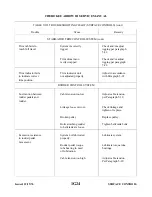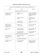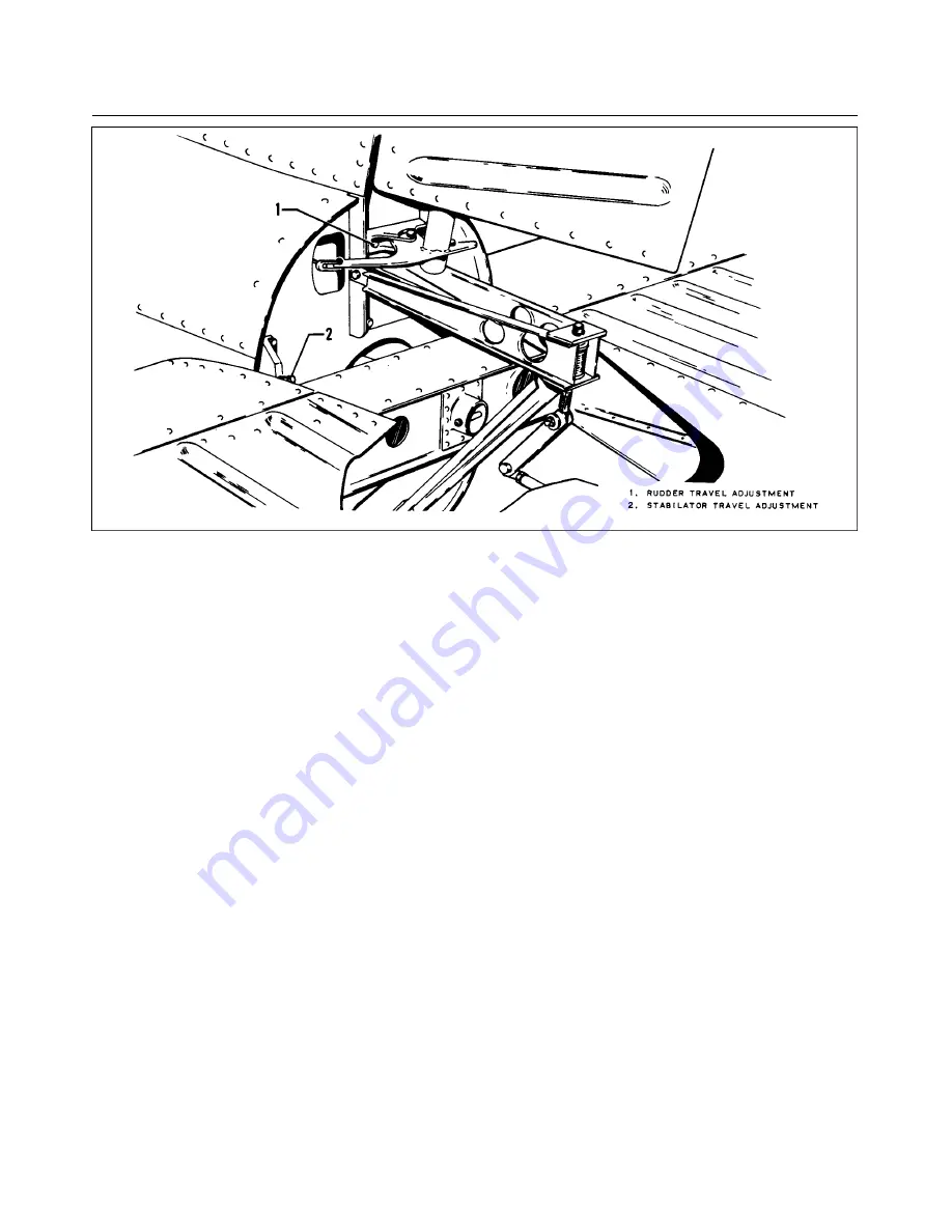
Figure 5-13. Rudder and Stabilator Travel Adjustments
5. Check safety of turnbuckles.
c.
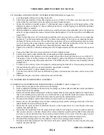
Adjust the rudder pedal stops by pushing on the pilots left rudder pedal until the rudder stop is
contacted. Adjust the pedal stop (on the fire wall) to provide 0.060 to 0.120 of an inch clearance.
Repeat the procedure with the copilots right rudder pedal. Do not push rudder harder then necessary to
avoid cable stretch.
d. Install the tail cone fairing and the access panel to the aft section of the fuselage.
5-30. RUDDER TRIM CONTROLS.
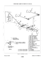
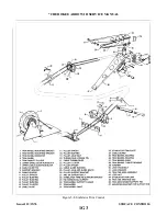
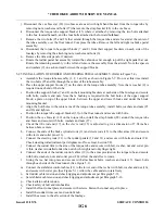
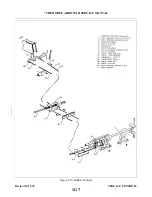
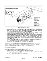
5-31. REMOVAL OF RUDDER TRIM CONTROLS. (Refer to Figure 5-14.)
a.
Remove the cover (1) from over the trim control assembly by removing attaching screws.
b. Remove the rudder trim knob (2) and the cover attaching screws.
c.
Rotate the trim knob to the extreme left (counterclockwise) trim position.
d. Disconnect the housing lug from the arm on the rudder pedal torque tube by removing cotter pin, nut,
e.
Remove the threaded bushing (4) from the aft end of the mounting channel (8) by removing cotter pin
and clevis pin (5). Some mounting channels have two holes in the aft end, note from which hole in the
clevis pin was removed.
f.
The mounting channel may be removed by removing the channel attaching screws at the inside of the
channel.
5-32. INSTALLATION OF RUDDER TRIM CONTROLS. (Refer to Figure 5-14.)
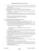
Install the rudder trim mechanism and set it at the neutral (no lead on spring) position. Perform the
procedure only after all other rudder and nose wheel rigging is complete.
a.
Install the trim control mounting channel (8) on the upper side of the floor tunnel. A spacer plate (14)
on some models is installed between the channel and the tunnel. Install the attaching screws (9) which
are secured with anchor nuts.
Issued: 12/15/76
1G10
* CHEROKEE ARROW III SERVICE MANUAL
SURFACE CONTROLS
Summary of Contents for ARROW III
Page 4: ...THIS PAGE INTENTIONALLY LEFT BLANK 1A4...
Page 12: ...THIS PAGE INTENTIONALLY LEFT BLANK 1A12...
Page 94: ...Figure 4 2 Wing Installation Revised 2 13 89 1D22 CHEROKEE ARROW III SERVICE MANUAL STRUCTURES...
Page 171: ...lH3 INTENTIONALLY LEFT BLANK...
Page 172: ...lH4 INTENTIONALLY LEFT BLANK...
Page 286: ...THIS PAGE INTENTIONALLY LEFT BLANK Revised 2 13 89 2A8...
Page 528: ...INTENTIONALLY LEFT BLANK 2K10 THRU 2L24 2K10...

