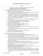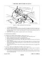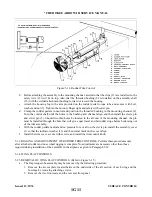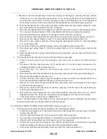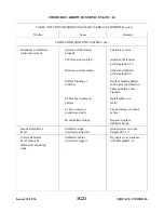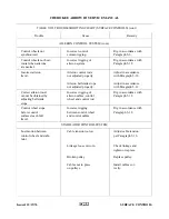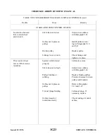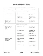
If the chain is not installed because of the torque tube assembly is removed, install the assembly as
per Step c instruction. Apply partial tension to cable to keep it positioned on pulley.
t u n n e l .
7 . Pull the flap handle (29) full back and connect the tension spring (22) to the cable end.
d .
Install the tunnel cover and secure with screws. Also, install the tunnel carpet and bracket cover.
e .
Install and secure the seats.
5-37. RIGGING AND ADJUSTMENT OF WING FLAPS.
a .
Place the flap control lever in the full forward (flaps up) position.
b .
Remove rear seats and floorboard to gain access to the flap torque tube.
c .
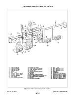
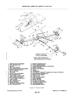
To adjust the flap up stop and step lock, first back off the left torque tube stop screw.
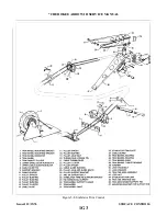
d . Adjust the right torque stop screw to obtain approximately 0.60 inch between the stop fitting and the
bearing back. (Refer to Figure 5-16.)
e .
With 0.60 inch obtained, and the right stop screw against its stop, tighten the lock nut, securing the stop
s c r e w.
f .
Adjust the left stop screw to make contact with the left stop.
g . Adjust the left upper tension spring, chain and cable. With the flap handle in the “flaps up” full forward
position, adjust the turnbuckle to remove all slack. Do not tighten cable to a point that the stop screw
comes off the stop.
h . Install the lower tension spring with the flap handle in the “flaps filll down” position.
i .
Place a 0.125 inch spacer between the right stop screw and stop fitting. With the right flap installed and
its flap control rod connected, determine that while exerting “down” pressure on the top of the flap will
not allow the flap to come down. If the flap extends, turn the stop screw out until “down” pressure on the
top of the flap will not allow the flap to go down.
j .
Adjust the left stop screw to match the right, then tighten its lock nut and remove the 0.125 inch spacer.
k .
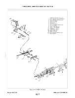
To set the flap control tension, remove the flap handle cover and tunnel access cover. Set the flap control
handle to the 0 degree position (handle forward, next to floor). Adjust the turnbuckle in the tunnel to
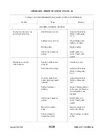
obtain 10 lb. +/- 1 lb. tension on the cable as per instructions given in Table V-I. When this operation is
completed, safety the turnbuckle.
N O T E
Do not rotate the torque tube, or allow the tube to be pulled away from the
stops in any way, when tensioning the cable.
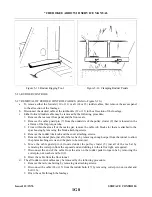
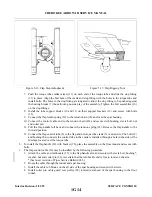
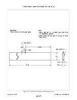
1 . With the flap handle in the “flaps up” position, check the up-neutral position by placing the flap rigging
tool (shown in Figure 5-17) against the bottom of the wing and each flap at a point as close as possible to
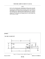
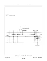
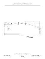
the outboard end of the flap. Ensure that the tool is not contacting any rivets. This tool may be fabricated
firm dimension data given in Figure 5-19.)
m . Adjust both flap push rods, which are connected between the right and left end of the torque tube and
each flap, until contact is made between the surface of the wing and the forward surface to the tool, and
the trailing edge of the flap is in contact with the aft end of the tool, so that the chord line of the flaps
form a +/- 1 degree angle with the wing chord at the outboard end of the flap(s). Maintain a light “up”
pressure on the underside of the flap (sufficient to take the slack out of the linkage) while adjusting the
r o d s .
the first notch, 25 +/- 2 degrees for the second notch, and 40 +/- 2 degrees for the third notch. If for any
reason, the settings cannot be obtained, then the torque tube stop screws will require readjustments, and a
review of the entire procedure. When a check of the flap operation is complete, then install all access
plates, and panels.
Revised: 2/13/89
1G15
* CHEROKEE ARROW III SERVICE MANUAL
SURFACE CONTROLS
Summary of Contents for ARROW III
Page 4: ...THIS PAGE INTENTIONALLY LEFT BLANK 1A4...
Page 12: ...THIS PAGE INTENTIONALLY LEFT BLANK 1A12...
Page 94: ...Figure 4 2 Wing Installation Revised 2 13 89 1D22 CHEROKEE ARROW III SERVICE MANUAL STRUCTURES...
Page 171: ...lH3 INTENTIONALLY LEFT BLANK...
Page 172: ...lH4 INTENTIONALLY LEFT BLANK...
Page 286: ...THIS PAGE INTENTIONALLY LEFT BLANK Revised 2 13 89 2A8...
Page 528: ...INTENTIONALLY LEFT BLANK 2K10 THRU 2L24 2K10...

