4 . Draw the armature from the motor frame (9). Note the number of thrust washers (11) mounted on
the drive end of the armature shaft.
5 . Remove the motor frame from the pump reservoir (13).
c .
The valve body and gear case assembly (15) may be separated from the reservoir (13) as follows:
1 .
Remove the screws from the flange of the body and separate the two assemblies.
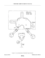
2 . The pump gears and valves should be removed for cleaning purposes only. To remove cap securing
gears, remove cap attaching bolts. There are two valve springs that should be positively identified
with their valve cavities. Otherwise, it will be necessary to readjust each valve for proper operating
p r e s s u r e .
N O T E
The Oildyne hydraulic pump is a sealed unit and inspection and repair
instructions are available from the vendor (manufacturer) only at this time.
6-7. CLEANING, INSPECTION AND REPAIRS OF HYDRAULIC PUMP. (PRESTO L I T E )
a .
Discard all old O-rings.
b . Remove cap or plugs and clean all parts with a dry type cleaning solvent and dry thoroughly.
N O T E
The conditions at repair require cleanliness, carefulness and proper
handling of parts. Ensure the foreign materials are prevented from entering
the system and that no parts are damaged.
c .
Inspect pump components for scratches, scores, chips, cracks and wear.
d . Inspect motor for worn brushes (minimum of .218 of an inch brush remains between the braided wire
and commutator end), excess commutator wear and excess bearing wear.
e .
Repairs are limited to O-ring and brush replacement as follows:
1 . One brush holder has the winding wire attached. Locate this wire and remove by using a soldering
g u n .
2 . The head assembly can now be removed and worked on for ease of brush replacement if required.
3 . Remove brush wire and brush from bimetal heat protector.
4 .
Solder new brush wires to head assembly and bimetal heat protector and wire from winding to one
brush holder.
5 . Install brush springs and brushes into brush holders and secure in place (temporary) with a piece of
string looped around the brush and holder and tied in a knot.
N O T E
Ensure that the braided wire is in the holder slot for proper brush movement.
6 .
Install the head assembly with new brushes to the frame and commutator in accordance with
instructions given in Paragraph 6-8, Step a.
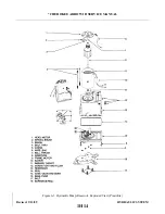
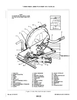
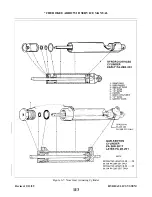
6-8. ASSEMBLY OF HYDRAULIC PUMP. (PRESTOLITE) (Refer to Figure 6-3.)
a .
The pump motor may be assembled and installed to the pump reservoir assembly as follows:
1 . Position the motor frame (9) on the reservoir (13). Note the aligning marks on the frame and
r e s e r v o i r.
2 . Place thrush washers (l 1), of the same amount removed, on the drive end of the armature (8).
3 .
Lubricate the entire length of the armature shaft, on the drive end, with a light grease to protect the
O-ring seal from damage and insert the end of the shaft in the reservoir.
4 .
Saturate the felt oiling pad around the commutator end bearing with SAE 20 oil. Allow excess oil to
drain off the assembling motor.
Revised: 2/13/89
1H13
* CHEROKEE ARROW III SERVICE MANUAL
HYDRAULIC SYSTEM
Summary of Contents for ARROW III
Page 4: ...THIS PAGE INTENTIONALLY LEFT BLANK 1A4...
Page 12: ...THIS PAGE INTENTIONALLY LEFT BLANK 1A12...
Page 94: ...Figure 4 2 Wing Installation Revised 2 13 89 1D22 CHEROKEE ARROW III SERVICE MANUAL STRUCTURES...
Page 171: ...lH3 INTENTIONALLY LEFT BLANK...
Page 172: ...lH4 INTENTIONALLY LEFT BLANK...
Page 286: ...THIS PAGE INTENTIONALLY LEFT BLANK Revised 2 13 89 2A8...
Page 528: ...INTENTIONALLY LEFT BLANK 2K10 THRU 2L24 2K10...

