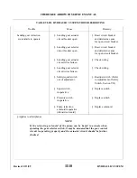
N O T E
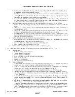
During test Steps 5 thru 7, there should not be any external leakage.
8 .
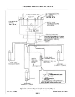
Should it be necessary to check the pump motor, first connect the ammeter in the electrical circuit with
the positive terminal of the meter to the black lead and the negative terminal of the meter to negative
terminal of the DC power supply.
9 .
Connect the blue lead to the positive terminal of the power supply. With the high pressure indication
within the 2250 +/-250 psi range on the pressure gauge, the ammeter should read between 35 to 60
amperes. Disconnect the electrical lead.
1 0 . Connect the green lead to the positive terminal of the power supply. With the high pressure indication
within the 500 to 800 psi range, the ammeter should read between 15 to 35 amperes.
N O T E
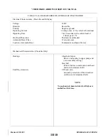
In the event that any of the various tests do not perform satisfactorily, the
pump assembly should be overhauled or replaced.
11 . Connect the green lead to the power supply to drop pressures before disconnecting the hydraulic lines.
6-10. INSTA L L ATION OF HYDRAULIC PUMP.
a .
Install the rubber shock mounts through the mounting holes of the pump. Insert a bushing through the
holes of each shock mount.
c .
Connect the hydraulic lines to the pump.
d .
Connect the pump electrical leads. Green wire to outboard relay, blue wire to inboard relay and black wire
to ground on battery shelf.
e .
Check fluid level in pump. Fill per instructions given in Section II.
f .
With the airplane on jacks, operate the pump to purge the hydraulic system of air, and check for leaks.
After operation, recheck fluid level.
6 - 11. GEAR BACK-UP EXTENDER ACTUATOR ASSEMBLY.
WA R N I N G
Piper considers service bulletins of extreme importance and compliance is
m a n d a t o r y.
N O T E
The following paragraphs, 6-11 through 6-14a, on grid pages 1H16 through
1H21, are instructions directed towards owners who have opted to comply with
Piper Service Bulletin 866A Part II, and keep the back-up gear extender
system operational.
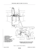
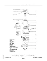
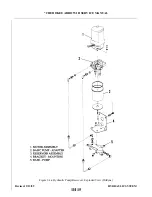
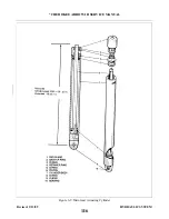
6-12. REMOVAL OF GEAR BACK-UP EXTENDER ACTUATOR ASSEMBLY. (Refer to Figure 6-6.) The
back-up extender actuator is located under the rear seat. To reach the actuator, remove the rear seats.
a .
Disconnect the actuator electrical leads at the quick disconnect terminals.
b .
Disconnect the pressure (13) and static (11) hoses from the elbows (12) of the diaphragm housing (10) by
releasing clamps and sliding the hoses from their elbows. The hoses should be tagged for ease of
r e a s s e m b l y.
c .
Place a shop cloth under the actuator hydraulic valve (25) to absorb fluid and then disconnect the hydraulic
lines (5) and (26) from the elbows (4) and (27) of the hydraulic valve (25). Cover the lines to prevent
c o n t a m i n a t i o n .
d .
Remove the machine screws that secure the actuator base to the mounting brackets. There are two
mounting screws at the inboard side of the base and one at the outboard side of the diaphragm housing.
Remove the actuator from the mounting brackets.
Revised: 2/13/89
1H19
* CHEROKEE ARROW III SERVICE MANUAL
HYDRAULIC SYSTEM
Summary of Contents for ARROW III
Page 4: ...THIS PAGE INTENTIONALLY LEFT BLANK 1A4...
Page 12: ...THIS PAGE INTENTIONALLY LEFT BLANK 1A12...
Page 94: ...Figure 4 2 Wing Installation Revised 2 13 89 1D22 CHEROKEE ARROW III SERVICE MANUAL STRUCTURES...
Page 171: ...lH3 INTENTIONALLY LEFT BLANK...
Page 172: ...lH4 INTENTIONALLY LEFT BLANK...
Page 286: ...THIS PAGE INTENTIONALLY LEFT BLANK Revised 2 13 89 2A8...
Page 528: ...INTENTIONALLY LEFT BLANK 2K10 THRU 2L24 2K10...

