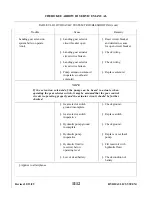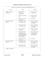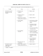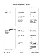
c.
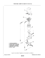
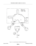
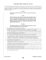
To check adjustment of electrical switch, the following procedure may be used:
1. Place the airplane on jacks. (Refer to Jacking, Section II.)
2. Move the mixture control back to idle cut-off and the throttle to fill forward to prevent gear
warning horn from sounding during adjustment.
3. Ascertain that the actuator tension springs are properly adjusted according to Step b.
4. Retract the landing gear hydro-electrically by turning the master switch ON, raising the emergency
gear extension lever and moving the gear selector handle to the up position. The emergency gear
extension lever must be retained in the up position to keep the gear up.
5. Check for proper switch operation by the following procedure:
(a) Turn master switch ON and move gear selector handle to the up position. Pump should not
operate.
(b) Move the emergency gear extension lever to the up override position. Pump should operate
and gear should retract.
(c) With selector lever up, slowly lower emergency gear extension lever to allow gear to drop to
down position. The pump should not operate at any time during extension.
(d) Turn master switch OFF.
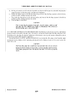
6. Check gear operation in the normal manner with the use of the gear selector handle. The
emergency extension lever must be held in the up override position.
7. Ascertain that gear is down and locked and remove airplane from jacks. Then flight check the
retractable landing gear system. (Refer to Paragraph 6-14a.)
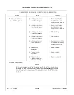
6-14a. OPERATION CHECK OF RETRACTABLE LANDING GEAR SYSTEM.
a.
Maximum Gear Extend: Place the gear selector in the down position at 129 KIAS. In approximately 5
to 10 seconds the three green gear lights should be on indicating that the gear is down and locked.
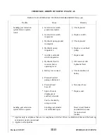
b. Minimum Gear Retract: Allow approximately 8 seconds for the pressure in the hydraulic system to
normalize between gear extension and retraction. Place the selector switch in the UP position at 107
KIAS. In approximately S to 10 seconds all the gear indicating lights should be out indicating that the
gear is filly retracted.
c
Override Gear Down and Up:
1. Down: Establish a normal glide at approximately 120 KIAS for PA-28R-201T or 110 KIAS for
PA-28R-201 with power at idle. Slowly move the override lever down, while observing the
ammeter to confirm that the hydraulic pump does not start. The gear should go down and lock.
Move the gear selector switch down. Release the override lever. The gear should remain down.
2. Up: Set maximum climb power. Maintain approximately 70 KIAS for PA-28R-201T or 65 KIAS
for PA-28R-201 for approximately 15 seconds. Move the gear selector switch to the up position.
The gear should not retract. Pull the override lever up. The gear should retract. Allow the airspeed
to increase to at least 115 KIAS for PA-28R-201T or 110 KIAS for PA-28R-201. Release the
override lever and the gear should remain up.
d. Gear “Back-Up” Down and Up:
l.
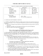
Gear Down: Set power at idle. Glide the aircraft at 120 KIAS for PA-28R-201T or 110 KIAS for
PA-28R-201. Decrease the airspeed at the rate of 1 knot per second. The gear should start down
between 101 and 109 KIAS for PA-28R-201T or 93 and 101 KIAS for PA-28R-201. Place the gear
selector switch down after the gear is down and locked.
2. Gear Up: Set maximum climb power. Maintain approximately 70 KIAS for PA-28R-201T or 65
KIAS for PA-28R-201 for approximately 15 seconds. Move the gear selector up. The gear should
stay down and locked. Increase the airspeed at the rate of 1 knot per second. The gear should begin
at to retract between 76 and 84 KIAS for PA-28R-201T or 73 and 81 KIAS for PA-28R-201 at
zero density altitude. The speed at which the gear starts up will increase 1 knot for PA-28R-201T
or 1.3 knots for PA-28R-201 for each 1000 increase of density altitude.
Revised: 2/13/89
1I1
* CHEROKEE ARROW III SERVICE MANUAL
HYDRAULIC SYSTEM
Summary of Contents for ARROW III
Page 4: ...THIS PAGE INTENTIONALLY LEFT BLANK 1A4...
Page 12: ...THIS PAGE INTENTIONALLY LEFT BLANK 1A12...
Page 94: ...Figure 4 2 Wing Installation Revised 2 13 89 1D22 CHEROKEE ARROW III SERVICE MANUAL STRUCTURES...
Page 171: ...lH3 INTENTIONALLY LEFT BLANK...
Page 172: ...lH4 INTENTIONALLY LEFT BLANK...
Page 286: ...THIS PAGE INTENTIONALLY LEFT BLANK Revised 2 13 89 2A8...
Page 528: ...INTENTIONALLY LEFT BLANK 2K10 THRU 2L24 2K10...

