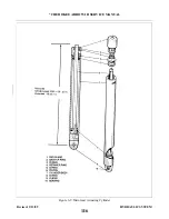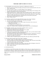
6-15. NOSE GEAR ACTUATING CYLINDER.
6-16. REMOVAL OF NOSE GEAR ACTUATING CYLINDER.
a.
Place the airplane on jacks. (Refer to Jacking, Section II.)
b. Disconnect the hydraulic lines from the actuating cylinder and cover the open line ends to prevent
contamination.
c.
Disconnect the cylinder operating rod end from the downlock hook by removing attachment nut and
bolt.
d. Disconnect the cylinder from its attachment fitting by removing nut and bolt.
e.
Remove the cylinder from the wheel well.
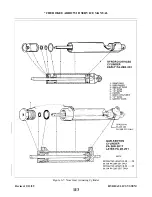
6-17. DISASSEMBLY OF NOSE GEAR ACTUATING CYLINDER. (Refer to Figure 6-7.)
a.
c.
6-18. CLEANING, INSPECTION, AND REPAIR OF NOSE GEAR ACTUATING CYLINDER.
a.
Clean the cylinder parts with a suitable dry type solvent and dry thoroughly.
b. Inspect the cylinder assembly for the following:
1. Interior walls of the cylinder and exterior surfaces of the piston for scratches, burrs, corrosion, etc.
2. Threaded areas for damage.
3. Rod end fitting and swivel fitting of cylinder for wear, cracks and corrosion.
4. O-rings for damage.
c.
Repairs to the cylinder and limited to polishing out small scratches, burrs, etc. and replacing parts.
6-19. ASSEMBLY OF NOSE GEAR ACTUATING CYLINDER. (Refer to Figure 6-7.)
a.
Install O-ring (5) on the exterior of the end gland (2).
back-up (3) with the O-ring (4).
c.
Install O-ring (8) on the body of the piston assembly.
d. Install the spacer into the cylinder body if applicable.
e.
Lubricate the areas around the O-rings with hydraulic fluid, slide the end gland on the piston rod and
the piston into the cylinder housing (7).
f.
Secure the end gland in the cylinder by installing the snap ring (1) in the annular slot in the Syncro
Devices cylinder. The end gland on the Gar-Kenyon cylinder is secured by threading gland into
cylinder body (7) and securing with safety wire (9).
g. Install restrictor fitting in the piston rod end of the cylinder.
h. Check smoothness of operation of the piston.
Revised: 2/13/89
1I4
* CHEROKEE ARROW III SERVICE MANUAL
HYDRAULIC SYSTEM
Summary of Contents for ARROW III
Page 4: ...THIS PAGE INTENTIONALLY LEFT BLANK 1A4...
Page 12: ...THIS PAGE INTENTIONALLY LEFT BLANK 1A12...
Page 94: ...Figure 4 2 Wing Installation Revised 2 13 89 1D22 CHEROKEE ARROW III SERVICE MANUAL STRUCTURES...
Page 171: ...lH3 INTENTIONALLY LEFT BLANK...
Page 172: ...lH4 INTENTIONALLY LEFT BLANK...
Page 286: ...THIS PAGE INTENTIONALLY LEFT BLANK Revised 2 13 89 2A8...
Page 528: ...INTENTIONALLY LEFT BLANK 2K10 THRU 2L24 2K10...

