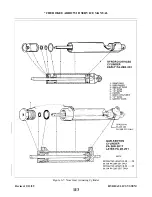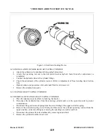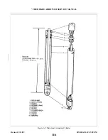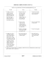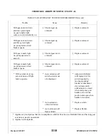
6-23. DISASSEMBLY OF MAIN GEAR ACTUATING CYLINDER. (Refer to Figure 6-9.)
a .
With the cylinder removed from the airplane, push the piston rod (6) (by hand) toward the clevis (9) to
remove oil from the unit.
b .
Put clevis (9) only in a soft jaw vise and clamp against the clevis bearing (10).
c .
If no pipe fitting is installed in the port of the end gland (1), install a fitting (1/8-27) into the port. This
fitting need not be tight as it will be used for leverage only.
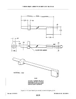
cylinder body (7). Reverse rotation of the gland to allow the lock ring to move out of the slot. (Refer to
Figure 6-8.) (It may be necessary to give the ring an assist to start out of the slot. If so, insert a strong
wire pick or other available tool in the slot to lift up the end of the ring and then rotate gland.)
e .
Pull the piston (6) and end gland from the cylinder.
f .
Remove O-ring as desired.
6-24. CLEANING, INSPECTION AND REPAIR OF MAIN GEAR ACTUATING CYLINDER.
a .
Clean the cylinder parts with a suitable dry type solvent and dry thoroughly.
b . Inspect the cylinder assembly for the following:
1 .
Interior walls of cylinder and exterior surfaces of piston for scratches, burrs, corrosion, etc.
2 . Threaded areas for damage.
3 . End fitting retainer slot for excess wear.
4 .
Rod end fitting and swivel fitting of cylinder for wear and collision.
c .
Repairs to the cylinder are limited to polishing out small scratches, burrs, etc, and replacing parts.
6-25. ASSEMBLY OF MAIN GEAR ACTUATING CYLINDER. (Refer to Figure 6-9.)
a .
Install O-ring (5) on the exterior of the end gland (1).
b . Install O-ring (3) and back-up ring (2) in the interior of the end gland.
c .
Install O-ring (8) on the body of the piston assembly.
d . Lubricate the areas around the O-rings with hydraulic fluid, park-o-lube or vaseline, slide the end gland
on the piston rod and the piston into the cylinder housing (7).
the end gland (1). Rotate gland counterclockwise to completely wrap lock ring into assembly.
f .
Align port in end gland and cylinder body.
g . Check smoothness of operation of piston and static pressure test unit to check for possible cut O-rings.
‘
6-26. INSTA L L ATION OF MAIN GEAR ACTUATING CYLINDER.
a .
Attach the cylinder to its attachment fitting in the wheel well using bolt and nut.
b . Attach the operating rod end and downlock spring swivel fitting to the upper side brace retraction fitting
by using bolt, washer and nut. Ascertain swivel fitting is free to rotate.
c .
Connect the downlock spring to the swivel fitting.
d .
e .
Operate pump to purge system of air and check fluid level in reservoir.
f .
Remove airplane from jacks.
6-27. HYDRAULIC LINES.
6-28. REMOVAL AND INSTA L L ATION OF HYDRAULIC LINES. Remove a damaged hydraulic line by
disconnecting the fitting at each end and by disconnecting where secured by brackets. Refer to Figure 6-2 as an
aid in the location of attaching brackets and bends in the lines. Provide a small container for draining the line.
Install a new or repaired line in reverse. Operate the pump to purge the system of air and check fluid level in
r e s e r v o i r.
Revised: 2/13/89
1I7
* CHEROKEE ARROW III SERVICE MANUAL
HYDRAULIC SYSTEM
Summary of Contents for ARROW III
Page 4: ...THIS PAGE INTENTIONALLY LEFT BLANK 1A4...
Page 12: ...THIS PAGE INTENTIONALLY LEFT BLANK 1A12...
Page 94: ...Figure 4 2 Wing Installation Revised 2 13 89 1D22 CHEROKEE ARROW III SERVICE MANUAL STRUCTURES...
Page 171: ...lH3 INTENTIONALLY LEFT BLANK...
Page 172: ...lH4 INTENTIONALLY LEFT BLANK...
Page 286: ...THIS PAGE INTENTIONALLY LEFT BLANK Revised 2 13 89 2A8...
Page 528: ...INTENTIONALLY LEFT BLANK 2K10 THRU 2L24 2K10...

