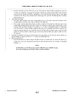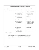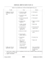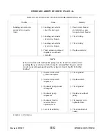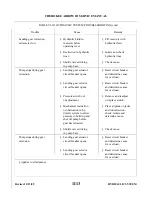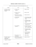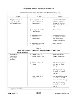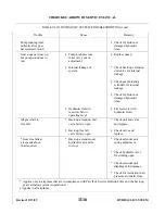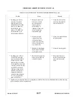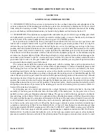
6-29. TESTING HYDRAULIC SYSTEM. The hydraulic system should be tested to determine that it functions
properly when suspicion of a problem exists, or after performing any service or repairs, it is suggested that the
airplane be connected to an outside source of power in order to conserve the battery. (Refer to External Power
Receptacle, Section II.)
CAUTION
Turn the master switch OFF before inserting or removing external power
supply plug.
NOTE
The following instructions will be directed towards testing that involves
systems incorporating the Prestolite and Oildyne hydraulic pumps. During
all tests, add hydraulic fluid MIL-H-5606 to reservoir as necessary to keep
fluid level visible to a level 1/2 inch below top of the filler hole on the
Prestolite pump, and to the FULL indication on the dipstick, with the
dipstick turned all the way in.
CAUTION
After filling the Oildyne reservoir, tighten dipstick, then back off 1 1/2 turns.
This is essential to allow the reservoir to be vented.
a.
Place airplane on jacks. (Refer to Jacking, Section II.)
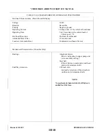
b. With gear down, master switch ON, and circuit breaker IN, or closed, check to see that there are three
green lights, the red warning light is OFF and that the gear warning horn is not sounding.
c.
Now place the landing gear in the UP position. Note that the pump operates immediately and the red
gear unsafe light illuminates on the instrument panel until the gear is fully retracted. The hydraulic
pump should stop operating after full gear retraction.
d. Place the gear in the DOWN position. The gear should extend and lock in position and the three green
gear position lights will illuminate when all three gears are locked in the down position.
e.
For airplanes that have complied with Piper Service Bulletin 866A, Part II and have the gear back-up
extender system operational, refer to Paragraph 6-14 for Check and Adjustment Procedures.
f.
Airplanes with the electric flap system incorporated, ensure that the flaps are rigged properly.
g. Put the gear selector in the up position. Check again that the gear retracts normally, that the pump
stops, and the red warning light goes out.
h. Put the flap selector in the first down (10 degree) position, and ensure that the flaps operate normally
to first position, and that the horn does not sound.
i.
Put the flap selector in the second down (25 degree) position, and ensure that the flaps operate
normally to second position, and that the horn does not sound.
j.
Put the flap selector in the fill down position, and observe that the flaps operate normally to the fill
down position, and that the horn continues to sound.
k. Return the flap selector to the first down (10 degree) position and check that they operate to first
position and that the warning horn stops sounding.
1. Now return the flaps to the full up (0 degree) position and check that the flaps have fully retracted and
the warning horn does not sound.
Revised: 2/13/89
1I8
* CHEROKEE ARROW III SERVICE MANUAL
HYDRAULIC SYSTEM
Summary of Contents for ARROW III
Page 4: ...THIS PAGE INTENTIONALLY LEFT BLANK 1A4...
Page 12: ...THIS PAGE INTENTIONALLY LEFT BLANK 1A12...
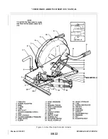
Page 94: ...Figure 4 2 Wing Installation Revised 2 13 89 1D22 CHEROKEE ARROW III SERVICE MANUAL STRUCTURES...
Page 171: ...lH3 INTENTIONALLY LEFT BLANK...
Page 172: ...lH4 INTENTIONALLY LEFT BLANK...
Page 286: ...THIS PAGE INTENTIONALLY LEFT BLANK Revised 2 13 89 2A8...
Page 528: ...INTENTIONALLY LEFT BLANK 2K10 THRU 2L24 2K10...

