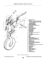
7-10. CLEANING, INSPECTION AND REPAIR OF NOSE LANDING GEAR
a.
Clean all parts with a suitable dry type cleaning solvent.
b. Inspect the gear components for the following unfavorable conditions:
1. Bolts, bearings and bushings for excess wear, corrosion and damage.
2. Gear housing, drag links, torque links, and tension spring arm for cracks, bends or misalignment.
3. Downlock hook for excess wear of the hook and bearing surfaces.
4. Downlock roller bearing for freedom of movement and excessive wobble.
c.
Inspect the gear tension and downlock hook springs for the following:
1. Excess wear or corrosion, especially around the hook portion of the springs. A spring should be
rejected if wear or corrosion exceeds one-quarter the diameter of the spring. Clean away all
corrosion and repaint.
2. Check the gear tension springs for load tensions below minimum allowable tolerances. The
minimum allowable tension of the inner spring is 37 pounds pull at 13.75 inches and the outer is
60 pounds pull at 13.75 inches. Measurement is taken from the inner side of each hook. If it is
found that either spring should be rejected, replace both springs.
3. Check the gear downlock hook spring for load tension below minimum allowable tolerance. The
minimum tension of the spring is 10.5 pounds pull at 4.5 inches. Measurement is also taken from
the inner side of each hook.
d. Check the general condition of each limit switch and its actuator, and wiring for fraying, poor
connections or conditions that may lead to failures.
e.
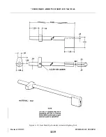
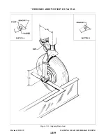
Check drag link through center travel by attaching the upper and lower drag links, setting them on a
surface table, and ascertaining that when the stop surfaces of the two links touch, linkage is not less
than .062 to .125 nor more than .125 to .250 of an inch through center. Should the distance exceed the
required through center travel and bolt and bushing are tight, replace one or both drag links.
f.
The shimmy dampener requires no service other than routine inspection. In case of damage or
malfunction, the dampener should be replaced rather than repaired.
g. Repair to the landing gear is limited to reconditioning of parts such as replacing bearings and
bushings, smoothing out minor nicks and scratches, repainting of areas where paint has chipped or
peeled and replacement of parts.
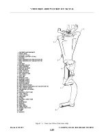
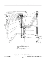
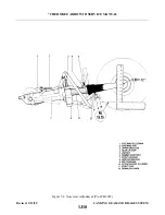
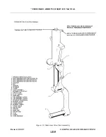
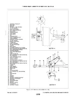
7-11. INSTALLATION OF NOSE LANDING GEAR. (Refer to Figure 7-2.)
NOTE
When assembling any units of the landing gear, lubricate bearings,
bushings, and friction surfaces with the proper lubricant as described in
Section II.
a.
Attach the steering bellcrank (4) with bushing to its mounting plate on the engine mount (36) securing
with the bolt assembly (13). Align the steering bellcrank (4) and the steering arm bushings (5) by
positioning the spacer washers as noted in removal. Connect the bungee assembly (1) to the bellcrank
(4) and install bolt and nut assemblies (3). The adjustment, fore and aft of the bellcrank, may be made
after the gear has been installed and rigged and adjusted.
b. To install the gear housing assembly, position the gear so that the bolt attachment points on the
Revised: 2/13/89
1J7
* CHEROKEE ARROW III SERVICE MANUAL
LANDING GEAR AND BRAKE SYSTEM
Summary of Contents for ARROW III
Page 4: ...THIS PAGE INTENTIONALLY LEFT BLANK 1A4...
Page 12: ...THIS PAGE INTENTIONALLY LEFT BLANK 1A12...
Page 94: ...Figure 4 2 Wing Installation Revised 2 13 89 1D22 CHEROKEE ARROW III SERVICE MANUAL STRUCTURES...
Page 171: ...lH3 INTENTIONALLY LEFT BLANK...
Page 172: ...lH4 INTENTIONALLY LEFT BLANK...
Page 286: ...THIS PAGE INTENTIONALLY LEFT BLANK Revised 2 13 89 2A8...
Page 528: ...INTENTIONALLY LEFT BLANK 2K10 THRU 2L24 2K10...

