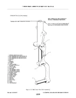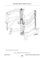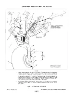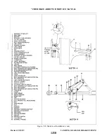
c.
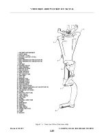
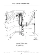
The drag links (32 and 35) and gear tension spring arm (40) may be installed by the following
procedure:
1. Ascertain that the upper and lower links (32 and 35) are assembled with the downlock hook
attached and the through travel of the links checked according to Paragraph 7-10.
2. Position the link assembly to allow the bolt holes in the links to align with the bolt holes in the
gear housing and the engine mount. Install the link attachment bolts.
3. Install nuts and washers on the upper link (35) attachment bolts. Tighten the nuts to allow the links
to rotate freely and safety.
4. Check alignment of the downlock hook to determine if it grips the roller bearing so as not to
contact the bolt head, the bearing attachment block or washer. If the downlock hook is inboard, or
it contacts the bolt head, shim between the bearing and the bearing attachment block with washer
AN960-10L, not to exceed three. The bearing must be free to rotate.
housing (39), secure and safety. A washer is installed on the bolt between the lower drag link and
the arm.
NOTE: During extension and retraction of the nose landing gear check the routing and security of the
mixture cable to prevent interference between the cable and the nose gear linkage.
d. Retract and extend the landing gear several times to ascertain smoothness of operation. Also check that
the drag link assembly falls into the through center-locked position.
e.
Retract the gear and connect the gear downlock spring (42) between the downlock hook (43) and the
upper drag link (35).
f.
Extend the gear and connect the two gear tension springs (15 and 17) between the attachment point on
the oleo housing (39) and the spring arm (40).
g. Ascertain that the landing gear is lubricated per Lubrication Chart, Section II.
h. Check adjustment of the gear per Paragraph 7-12 or 7-13.
i.
Install engine cowling. (The cowl support jacks located at each forward side of the nose gear door
hinges are adjusted down to contact the cowl surface after attaching screws are secure.)
j.
Retract landing gear and check door operation as per Paragraph 7-18.
k. Check the alignment of the nose gear per Paragraph 7-14.
l.
Ascertain that the landing gear is down and locked, then remove the airplane from jacks.
7-12.
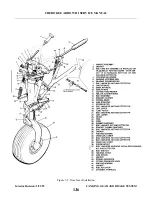
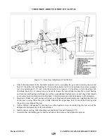
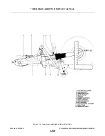
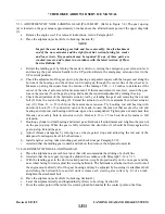
ADJUSTMENT OF NOSE LANDING GEAR (PA-28R-201). (Refer to Figure 7-3.) The gear up stop
(4) is located just above the gear door retraction roller near the lower aft end of the engine.
a.
Remove the engine cowl. For removal instructions, refer to Paragraph 8A-14.
b.
Place the airplane on jacks. (Refer to Jacking, Section II.)
NOTE: Inspect the nose landing gear link and brace assembly, the aft attachment end of the nose actuator
and the right front hat section fairing for cracks and loose rivets. Dye penetrant may be required.
If any of these parts are cracked, remove and replace in accordance with the latest revision of
Piper Service Bulletin 724.
c.
Retract the landing gear by turning the master switch on, raising the emergency gear extension lever
and moving the gear selector handle to the UP position. Retain the emergency extension lever in the
UP override position.
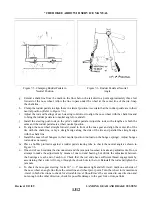
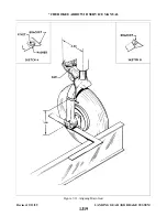
d. Check the adjustment of the gear up stop by placing a carpenters square with the longest end along the
bottom of the fuselage and the shortest end running up through the centerline of the wheel axle.
Measure up along the square from the bottom of the fuselage 5.80 +/- .12 inches to determine if the
center of the wheel axle meets this measurement. If this measurement is incorrect, extend the gear,
loosen the jam nut (5) on the gear up stop, and make the required adjustment by turning the stop.
Revised: 02/27/04
1J8
* CHEROKEE ARROW III SERVICE MANUAL
LANDING GEAR AND BRAKE SYSTEM
Summary of Contents for ARROW III
Page 4: ...THIS PAGE INTENTIONALLY LEFT BLANK 1A4...
Page 12: ...THIS PAGE INTENTIONALLY LEFT BLANK 1A12...
Page 94: ...Figure 4 2 Wing Installation Revised 2 13 89 1D22 CHEROKEE ARROW III SERVICE MANUAL STRUCTURES...
Page 171: ...lH3 INTENTIONALLY LEFT BLANK...
Page 172: ...lH4 INTENTIONALLY LEFT BLANK...
Page 286: ...THIS PAGE INTENTIONALLY LEFT BLANK Revised 2 13 89 2A8...
Page 528: ...INTENTIONALLY LEFT BLANK 2K10 THRU 2L24 2K10...

