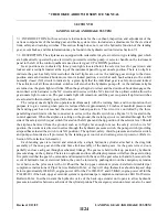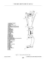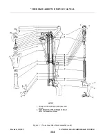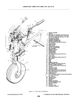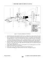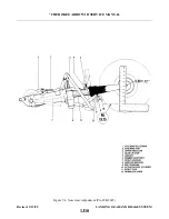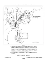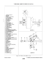
7-13. ADJUSTMENT OF NOSE LANDING GEAR (PA-28R-201T. (Refer to Figure 7-4.) The gear up stop
(4) is located on the gear mount approximately 6 inches above the aft attachment point of the upper drag link
(3).
a.
Remove the engine cowl. For removal instructions, refer to Paragraph 8-5.
b. Place the airplane on jacks. (Refer to Jacking, Section II.)
NOTE
Inspect the nose landing gear link and brace assembly, the aft attachment
end of the nose actuator and the right front hat section fairing for cracks
and loose rivets. Dye penetrant may be required. If any of these parts are
cracked, remove and replace in accordance with the latest revision of Piper
Service Bulletin 724.
c.
Retract the landing gear by turning the master switch on, raising the emergency gear extension lever
and moving the gear selector handle to the UP position. Retain the emergency extension lever in the
UP override position.
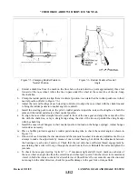
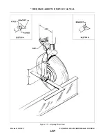
d. Check the adjustment of the gear up stop by placing a carpenters square with the longest end along the
bottom of the fuselage and the shortest end running up through the center line of the wheel axle.
Measure up along the square from the bottom of the fuselage 5.00 +/- .12 inches to determine if the
center of the wheel axle meets this measurement. If this measurement is incorrect, extend the gear,
loosen the jam nut (5) on the gear up stop, and make the required adjustment by turning the stop.
e.
Check the adjustment of the hydraulic actuator rod by extending the gear and removing the nut and
bolt (9) from the rod end bearing (8). Extend the actuator rod (10) to maximum then retract actuator
rod (10) from .33 to .53 inch from the maximum extension. Try hooking rod end bearing with
downlock hook (12), if connection can not be made, loosen the jam nut that secures the rod end
bearing and turn rod end bearing until hook-up can be accomplished. Tighten jam nut and check that
threads cover safety hole in actuator rod (6). Recheck .33 to. 35 inch rod travel remains to full
extension.
f.
Hook-up cylinder rod end bearing and retract gear. Recheck all adjustments and retighten the jam nut
on the gear up stop. When the gear is fully retracted, the strut tube (11) should be firmly against the
gear up stop. Extend the gear.
g. Adjust shimmy dampener by turning nose wheel against stops and adjusting the rod end of the
dampener for adequate travel to both extremes.
h. Install engine cowling, retract landing gear and check door per Paragraph 7-18.
i.
Ascertain that the landing gear is down and locked, then remove the airplane from jacks.
7-14. ALIGNMENT OF NOSE LANDING GEAR.
a.
Place the airplane on a smooth level door that will accommodate the striking of a chalk line.
b. Ascertain that the nose gear is properly adjusted in accordance with Paragraph 7-12 or 7-13.
c.
With the landing gear in the down-locked position, weight proportionally on the nose gear and the
nose wheel facing forward, adjust the steering bellcrank. The bellcrank is attached at the lower front of
the engine mount directly aft of the gear housing and may be adjusted by loosening its attachment bolt
and sliding the bellcrank fore and aft until it clears each steering arm rollers by .03 of an inch.
Retighten the attachment bolt.
d. Place the airplane on jacks. (Refer to Jacking, Section II.)
e.
Level the airplane laterally and longitudinally. (Refer to Leveling, Section II.)
f.
From the center point of the tail skid, extend a plumb bob and mark the contact point on the floor.
Revised: 2/13/89
1J11
* CHEROKEE ARROW III SERVICE MANUAL
LANDING GEAR AND BRAKE SYSTEM
Summary of Contents for ARROW III
Page 4: ...THIS PAGE INTENTIONALLY LEFT BLANK 1A4...
Page 12: ...THIS PAGE INTENTIONALLY LEFT BLANK 1A12...
Page 94: ...Figure 4 2 Wing Installation Revised 2 13 89 1D22 CHEROKEE ARROW III SERVICE MANUAL STRUCTURES...
Page 171: ...lH3 INTENTIONALLY LEFT BLANK...
Page 172: ...lH4 INTENTIONALLY LEFT BLANK...
Page 286: ...THIS PAGE INTENTIONALLY LEFT BLANK Revised 2 13 89 2A8...
Page 528: ...INTENTIONALLY LEFT BLANK 2K10 THRU 2L24 2K10...

