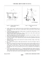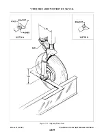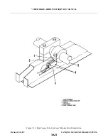
2. The arm assembly may be installed by placing the arms on either side of the bracket (8) and
securing with bolt, bushings, nut, washer and cotter pin (6).
3. Install the gear door(s) by positioning the hinge halves of the door and cowl and inserting the
hinge pin. It is recommended a new pin be used. Bend the end of the pin to secure in place.
4. Install the cowl and adjust doors as given in Paragraph 7-18.
7- 18. ADJUSTMENT OF NOSE GEAR DOORS.
a.
Adjust PA-28R-201 nose gear doors as follows:
1. Place the airplane on jacks. (Refer to Jacking, Section II.)
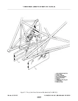
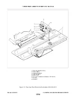
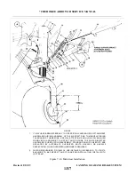
2. Adjust the door retraction rods so that the gear will swing through the door opening with a .12 +/-
.06 of an inch clearance between the gear and door at their closest point. This can best be done
with the nose gear down, tension springs disconnected and operating the nose gear manually.
3. With door clearance adjusted, adjust the link between the roller assembly and bellcrank assembly so
that the doors will pull up tightly when gear is full up. Over tightening may result in door
buckling, however if the link is too loose, doors will gap in flight.
4. Check all rod ends for adequate thread engagement, for safety and tightness of jam nuts.
5. Remove the airplane from jacks.
b. Adjust PA-28R-201T nose gear doors as follows:
1. Place the airplane on jacks. (Refer to Jacking, Section II.)
2. Gear up stop must be properly adjusted per Paragraph 7-17 before rigging doors.
3. Adjust the door actuator rods to fully close doors in the gear up position.
4. Check all rod ends for adequate thread engagement, for safety and tightness of jam nuts.
5. Remove the airplane from jacks.
7-19. MAIN LANDING GEAR SYSTEM.
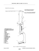
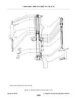
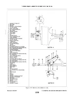
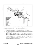
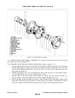
7-20. DISASSEMBLY OF MAIN GEAR OLEO. (Refer to Figure 7-9.) The main gear oleo assembly may be
removed and disassembled from the gear oleo housing with the gear removed from or installed on the airplane.
a.
Place the airplane on jacks. (Refer to Jacking, Section II.)
b. Place a drip pan under the main gear to catch spillage.
c.
Remove the air and fluid from the oleo. To do this, depress the air valve core pin until strut pressure
has diminished, remove the filler plug and with a small hose, siphon as much hydraulic fluid from the
strut as possible.
d. Disconnect the brake line at the joint located in the wheel well.
e.
To remove piston tube (25) assembly from oleo housing (11), remove the upper and lower torque link
connecting bolt assembly (3) and separate the links. Note number and thickness of spacer washer(s)
between the two links (15 and 16).
f.
Compress the piston tube (25), reach up along the tube and release the snap ring (24) from the annular
slot at the bottom of the oleo housing.
g. Pull the piston tube (25) with component parts from the cylinder housing.
h. The piston tube (25) components may be removed by reaching in the tube and pushing out the upper
i.
j.
k. To remove the piston tube plug (26) with O-ring (27) located in the lower end of the tube, remove the
bolt assembly and insert a rod up through the hole in the body of the fork (28), pushing the plug out
through the top of the tube.
Revised: 2/13/89
1J21
* CHEROKEE ARROW III SERVICE MANUAL
LANDING GEAR AND BRAKE SYSTEM
Summary of Contents for ARROW III
Page 4: ...THIS PAGE INTENTIONALLY LEFT BLANK 1A4...
Page 12: ...THIS PAGE INTENTIONALLY LEFT BLANK 1A12...
Page 94: ...Figure 4 2 Wing Installation Revised 2 13 89 1D22 CHEROKEE ARROW III SERVICE MANUAL STRUCTURES...
Page 171: ...lH3 INTENTIONALLY LEFT BLANK...
Page 172: ...lH4 INTENTIONALLY LEFT BLANK...
Page 286: ...THIS PAGE INTENTIONALLY LEFT BLANK Revised 2 13 89 2A8...
Page 528: ...INTENTIONALLY LEFT BLANK 2K10 THRU 2L24 2K10...

