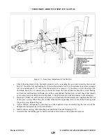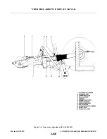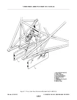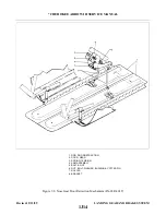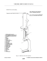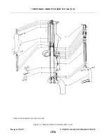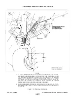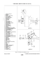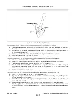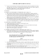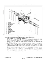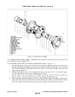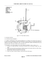
7-23. REMOVAL OF MAIN LANDING GEAR. (Refer to Figure 7-10.)
a.
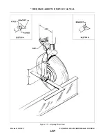
Place the airplane on jacks. (Refer to Jacking, Section II).
b. The side brace link assembly may be removed by the following procedure:
1. With the gear in the extended position, disconnect the gear downlock spring (18).
2. Disconnect the rod end (46) of the actuating cylinder (24) from the retraction fitting (21) of the
3. Disconnect the lower side brace link (33) from the gear housing (13) by removing the attachment
nut, washer and bolt (7). Note bushings on each side of the end bearing.
4. Disconnect the upper side brace link (28) from the side brace support fitting stud (26) by removing
the cotter pin, nut, washer and attachment bolt (25).
5. The side brace support fitting may be removed by removing the cap bolts that secure the fitting to
the web of the spar.
6. Remove the assembly and further disassemble and inspect as needed.
c.
The landing gear housing (13) with components may be removed by the following procedure:
1. Disconnect the brake line (42) at its upper end in the wheel well.
2. Disconnect the gear door actuating rod (38) at the gear housing.
3. Remove the access plate located on the underside of the wing, aft of landing gear.
4. If not previously disconnected, disconnect the lower side brace link (33) from the gear housing.
5. Disconnect the forward support fitting (16) of the housing (13) from the web of the main spar by
removing the fitting attachment bolts.
6. Remove the retainer tube (4) in the aft support fitting (1) that supports the aft arm of the housing
by reaching through the access opening on the underside of the wing, through the hole in the web
and removing the bolt (48) that secures the tube in the housing. Insert a hook through the bolt hole
in the tube and slide it aft from the support fitting. Remove the tube from the wing. Note the
number of spacer washers (52) between the arm and support fitting (1).
7. Allow the gear to drop down removing it from the wing.
8. The aft support fitting (1) may be removed by holding the nuts, reaching through the access
opening, and removing the fitting attachment bolts.
9. The forward support fitting (16) may be removed from the arm of the housing by removing the
bolt and washer from the base side of the fitting. Slide the fitting from the arm. Remove the
washer (52) from the arm.
(2) that hold the bearing in the housing. Push the bearing from the housing.
7-24. CLEANING, INSPECTION AND REPAIR OF MAIN LANDING GEAR.
a.
Clean all parts with a suitable dry type cleaning solvent.
b. Inspect the gear components for the following unfavorable conditions:
1. Bolts, bearing and bushings for excess wear, corrosion and damage.
2. Gear housing, side brace links, torque links and attachment plates for cracks, bends or
misalignment.
3. Downlock hook for excessive wear of the bearing surfaces.
c.
Inspect the gear downlock spring for the following:
1. Excessive wear or corrosion, especially around the hook portion of the spring. A spring should be
rejected if wear or corrosion exceeds one-quarter the diameter of the spring. Clean away all
corrosion and repaint.
2. Check the spring for load tensions below minimum allowable tolerance. The minimum tension of
the spring is 48 pounds pull at 7.9 inches. Measurement is taken from the inner side of each hook.
Revised: 2/13/89
1J23
* CHEROKEE ARROW III SERVICE MANUAL
LANDING GEAR AND BRAKE SYSTEM
Summary of Contents for ARROW III
Page 4: ...THIS PAGE INTENTIONALLY LEFT BLANK 1A4...
Page 12: ...THIS PAGE INTENTIONALLY LEFT BLANK 1A12...
Page 94: ...Figure 4 2 Wing Installation Revised 2 13 89 1D22 CHEROKEE ARROW III SERVICE MANUAL STRUCTURES...
Page 171: ...lH3 INTENTIONALLY LEFT BLANK...
Page 172: ...lH4 INTENTIONALLY LEFT BLANK...
Page 286: ...THIS PAGE INTENTIONALLY LEFT BLANK Revised 2 13 89 2A8...
Page 528: ...INTENTIONALLY LEFT BLANK 2K10 THRU 2L24 2K10...

