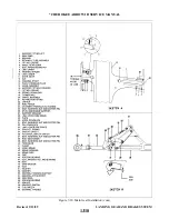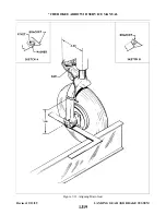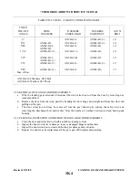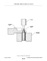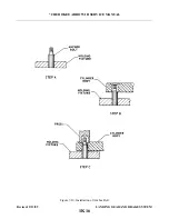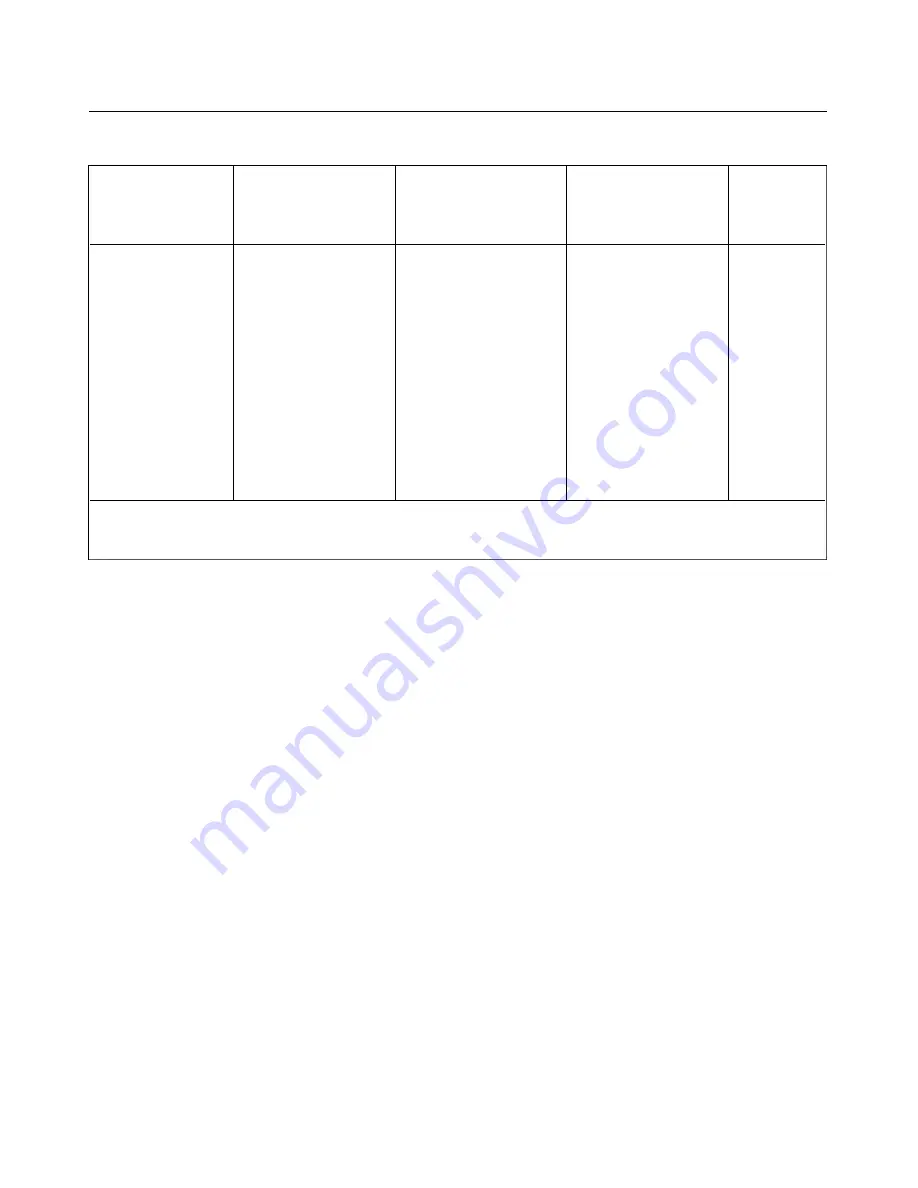
TABLE VII-I. TOE-IN—TOE-OUT CORRECTION CHART
TOE-IN
TOE-OUT
SHIM
WASHERS
WASHERS
AN 174
ANGLE
WASHERS
UNDER HEAD
UNDER NUT
BOLT
0
O
AN960-416
AN960-416 (3)
-14
0°33’
AN960-416
AN960-416
AN960-416 (2)
-14
0°48’
AN960-416L
AN960-416
AN960-416
-14
AN960-416
1 °04’
AN960-416 (2)
AN960-4 16
AN960-416
-14
l °l9’
AN960-416L
AN960-416L
AN960-416
-14
AN960-416 (2)
1°35’
AN960-416 (3)
AN960-416
AN960-416 (2)
-15
2°05’
AN960-416 (4)
AN960-416
AN960-416
-15
Max. Allow.
.
AN960-416L Washers .031 Thick
AN960-416 Washers .062 Thick
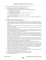
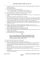
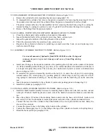
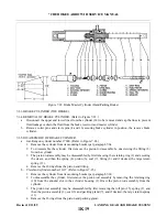
7-28. REMOVAL OF MAIN GEAR DOOR ASSEMBLY.
a.
With the landing gear extended, disconnect the door retraction rod from the door by removing nut,
washers and bolt.
b. Remove the door from the wing panel by bending the door hinge pin straight and from the other end
pulling out the pin.
c.
The door retraction rod may be removed from the gear housing by cutting the safety wire and
removing the attachment bolt and washer. Note the number of washers between rod end bearing and
housing.
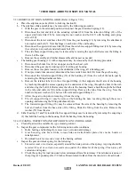
7-29. CLEANING, INSPECTION AND REPAIR OF MAIN GEAR DOOR ASSEMBLY.
a.
Clean the door and retraction rod with a suitable cleaning solvent.
b. Inspect the door for cracks or damage, loose or damaged hinges and brackets.
c.
Inspect the door retraction rod and end bearing for damage and corrosion.
d. Repairs to a door may be replacement of hinge, repair of fiberglass and painting.
Revised: 2/13/89
1K4
* CHEROKEE ARROW III SERVICE MANUAL
LANDING GEAR AND BRAKE SYSTEM
Summary of Contents for ARROW III
Page 4: ...THIS PAGE INTENTIONALLY LEFT BLANK 1A4...
Page 12: ...THIS PAGE INTENTIONALLY LEFT BLANK 1A12...
Page 94: ...Figure 4 2 Wing Installation Revised 2 13 89 1D22 CHEROKEE ARROW III SERVICE MANUAL STRUCTURES...
Page 171: ...lH3 INTENTIONALLY LEFT BLANK...
Page 172: ...lH4 INTENTIONALLY LEFT BLANK...
Page 286: ...THIS PAGE INTENTIONALLY LEFT BLANK Revised 2 13 89 2A8...
Page 528: ...INTENTIONALLY LEFT BLANK 2K10 THRU 2L24 2K10...

