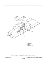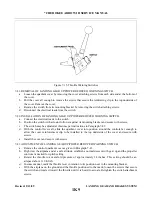
f.
Advance and retard the throttle to ascertain that the switch actuates at the desired throttle lever setting.
The airplane may also be down to ascertain that the horn and light will actuate when the throttle is
reduced below approximately 14 inches of manifold pressure with gear up.
g. Reinstall the quadrant cover as given in Paragraph 7-42.
7-44. WHEELS.
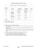
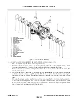
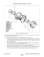
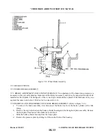
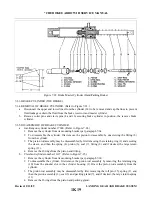
7-45. REMOVAL AND DISASSEMBLY OF NOSE WHEEL. (Refer to Figure 7-16.)
a.
b. To remove the nose wheel, first remove the cotter pin and washer that secures the safety clevis pin of
the wheel nut. Next remove the clevis pin, wheel nut and then slide the wheel from the axle.
c.
The wheel halves (7 and 10) may be separated by first deflating the tire. With the tire suff i c i e n t l y
deflated, remove the wheel through bolts (18). Pull the wheel halves from the tire by removing the
wheel half opposite the valve stem first and then the other half.
d. The wheel bearing assemblies may be removed from each wheel half by first removing the snap rings
7-46. INSPECTION OF NOSE WHEEL ASSEMBLY.
a.
Visually check all parts for cracks, distortion, defects and excess wear.
b. Check tie bolts for looseness or failure.
c.
Check internal diameter of felt grease seals. Replace the felt grease seal if surface is hard or gritty.
d. Check tire for cuts, internal bruises and deterioration.
e.
Check bearing cones and cups for wear and pitting and relubricate.
f.
Replace any wheel casting having visible cracks.
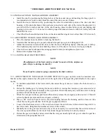
7-47. ASSEMBLY AND INSTALLATION OF NOSE WHEEL. (Refer to Figure 7-16.)
a.
Ascertain that the bearing cup (5 or 11) for each wheel half (7 and 10) is properly installed. Install the
tire with tube on the wheel half with the valve stem hole and then join the two wheel halves. Install the
through bolts (18) with the washer (9 and 17) and nuts (8) to the valve stem side.
NOTE
On aircraft models which use the Cleveland wheel assembly, torque nuts to
90 inch-pounds. Those aircraft models which use the McCauley wheel
assembly, torque nuts to 140-150 inch-pounds.
NOTE
On McCauley nose wheel assemblies only, bushing (19) is required to
prevent tube movement.
b. Position the tire and tube so the index mark on the tire is aligned with the index mark on the tube. This
c.
d. Slide the wheel on the axle and secure with retainer nut. righten nut to allow no side play, yet allow the
wheel to rotate freely. Safety the nut with clevis pin and secure pin with washer and cotter pin.
Revised: 2/13/89
1K10
* CHEROKEE ARROW III SERVICE MANUAL
LANDING GEAR AND BRAKE SYSTEM
Summary of Contents for ARROW III
Page 4: ...THIS PAGE INTENTIONALLY LEFT BLANK 1A4...
Page 12: ...THIS PAGE INTENTIONALLY LEFT BLANK 1A12...
Page 94: ...Figure 4 2 Wing Installation Revised 2 13 89 1D22 CHEROKEE ARROW III SERVICE MANUAL STRUCTURES...
Page 171: ...lH3 INTENTIONALLY LEFT BLANK...
Page 172: ...lH4 INTENTIONALLY LEFT BLANK...
Page 286: ...THIS PAGE INTENTIONALLY LEFT BLANK Revised 2 13 89 2A8...
Page 528: ...INTENTIONALLY LEFT BLANK 2K10 THRU 2L24 2K10...

