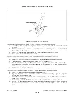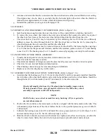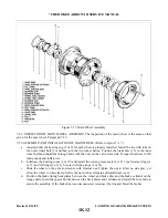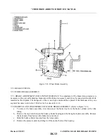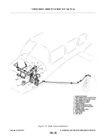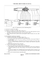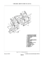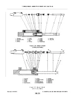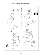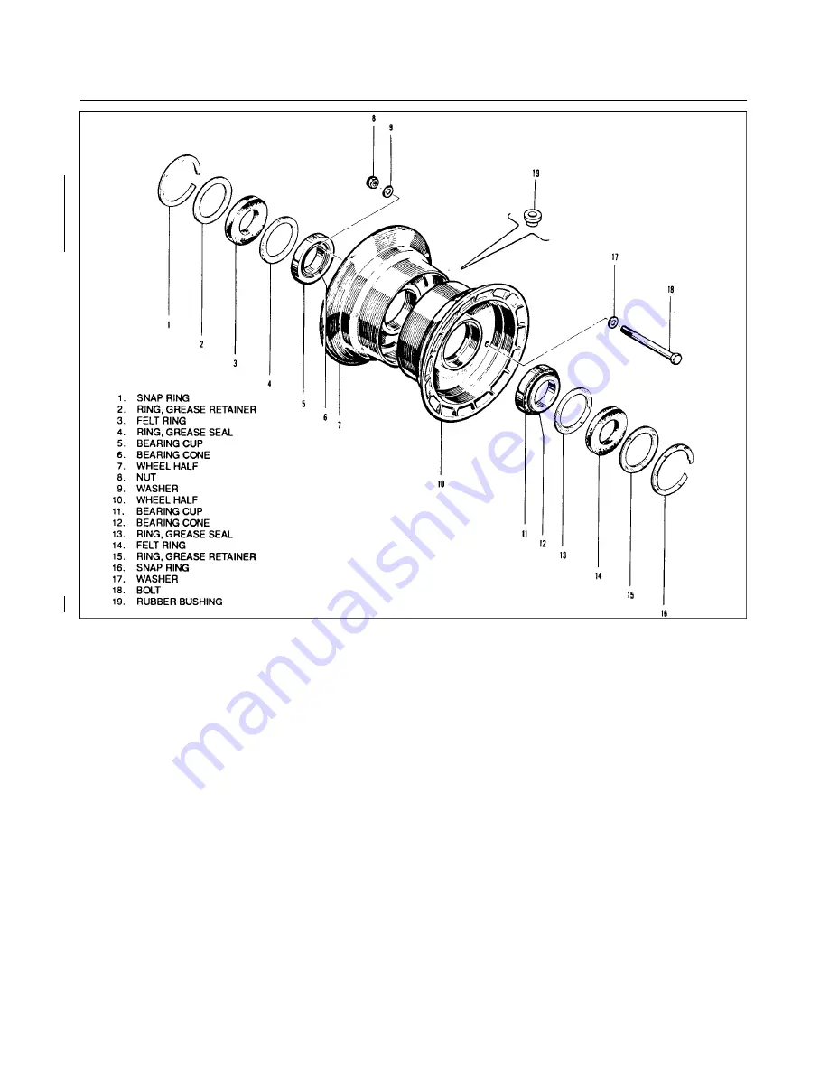
Figure 7-16. Nose Wheel Assembly
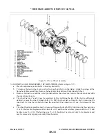
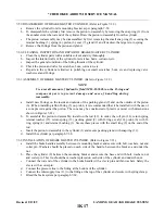
7-48. REMOVAL AND DISASSEMBLY OF MAIN WHEEL. (Refer to Figure 7-17.)
a.
Place the airplane on jacks. (Refer to Jacking, Section II.)
b. To remove the main wheel, remove the four cap bolts that join the brake cylinder housing and the
lining back plate assemblies. Remove the back plate from between brake disc and wheel.
c.
Remove the dust cover and the cotter pin that safeties the wheel nut, remove the wheel nut and slide
the wheel from the axle.
d. The wheel halves (7 and 8) may be separated by first deflating the tire. With the tire suff i c i e n t l y
e.
The wheel bearing assemblies may be removed from each wheel half by first removing the snap rings
(1 or 14) that secure the grease seal retainers (2 or 13) and then the retainers, grease seals (4 or 11) and
bearing cones (6 or 10). The bearing cups (5 or 9) should not be removed only for replacement and
may be removed by tapping out evenly from the inside.
Revised: 2/13/89
1K11
* CHEROKEE ARROW III SERVICE MANUAL
LANDING GEAR AND BRAKE SYSTEM
Summary of Contents for ARROW III
Page 4: ...THIS PAGE INTENTIONALLY LEFT BLANK 1A4...
Page 12: ...THIS PAGE INTENTIONALLY LEFT BLANK 1A12...
Page 94: ...Figure 4 2 Wing Installation Revised 2 13 89 1D22 CHEROKEE ARROW III SERVICE MANUAL STRUCTURES...
Page 171: ...lH3 INTENTIONALLY LEFT BLANK...
Page 172: ...lH4 INTENTIONALLY LEFT BLANK...
Page 286: ...THIS PAGE INTENTIONALLY LEFT BLANK Revised 2 13 89 2A8...
Page 528: ...INTENTIONALLY LEFT BLANK 2K10 THRU 2L24 2K10...

