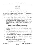
8-10. CLEANING, INSPECTION AND REPAIR OF PROPELLER.
NOTE
Do not attempt to disassemble the propeller any further than stated in this
manual. For internal repairs and replacement of parts, the propeller should
be referred to the Hartzell Factory or Certified Repair Station.
a.
Check for oil and grease leaks.
b. Clean the spinner, propeller hub, and blades with a non-corrosive solvent.
c.
Inspect the hub parts for cracks.
d. Steel hub parts should not be permitted to rust. Use aluminum paint to touch up, if necessary, or
replate them during overhaul.
e.
Check all visible parts for wear and safety.
f.
Check blades to determine whether they turn freely on the hub pilot tube. This can be done by rocking
the blades back and forth through the slight freedom allowed by the pitch change mechanism. If they
appear tight and are properly lubricated, the propeller should be disassembled by an authorized Service
Center.
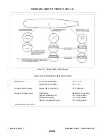
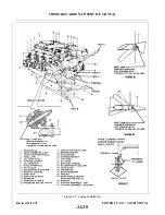
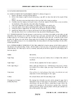
g. Inspect the blades for damage or cracks. Nicks in the leading edges of blades should be filed out and
all edges rounded, as cracks sometimes start from such places. Use fine emery cloth for finishing.
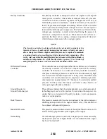
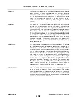
(Refer to Figure 8-4 for propeller blade care.)
h. Check the condition of the propeller mounting nuts and studs.
i.
Each blade face should be sanded lightly with fine sandpaper and painted, when necessary, with a flat
black paint to retard glare. A light application of oil or wax may be applied to the surfaces to prevent
corrosion.
j.
Grease the blade hub through the zerk fittings. Remove one of the two fittings for each propeller blade;
alternate the next time. Apply grease through the zerk fitting until fresh grease appears at the fitting
hole of the removed fitting. Care should be taken to avoid blowing out the hub gaskets.
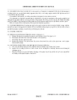
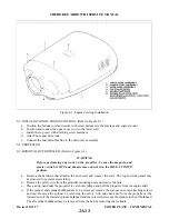
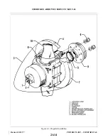
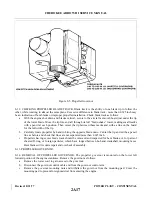
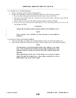
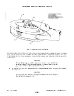
8-11. INSTALLATION OF PROPELLER. (Refer to Figure 8-3.)
WARNING
Before performing any work around the propeller be sure the magneto and
master switch is OFF, and the mixture control is in the IDLE CUT- O F F
position.
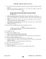
a.
Clean the propeller and engine flanges.
b. Lubricate and install the O-ring in the propeller hub.
c.
Align the propeller with the dowel pins on the prop flange and slide it over the pins.
d. Tighten the mounting nuts a few threads at a time until all are tight. Stager torque the nuts 60 to 70
foot-pounds.
e.
Safety the propeller mounting nuts.
f.
Install spinner if removed and torque screws 35 to 40 inch-pounds.
Revised: 12/11/78
2A15
CHEROKEE ARROW III SERVICE MANUAL
POWER PLANT - CONTINENTAL
Summary of Contents for ARROW III
Page 4: ...THIS PAGE INTENTIONALLY LEFT BLANK 1A4...
Page 12: ...THIS PAGE INTENTIONALLY LEFT BLANK 1A12...
Page 94: ...Figure 4 2 Wing Installation Revised 2 13 89 1D22 CHEROKEE ARROW III SERVICE MANUAL STRUCTURES...
Page 171: ...lH3 INTENTIONALLY LEFT BLANK...
Page 172: ...lH4 INTENTIONALLY LEFT BLANK...
Page 286: ...THIS PAGE INTENTIONALLY LEFT BLANK Revised 2 13 89 2A8...
Page 528: ...INTENTIONALLY LEFT BLANK 2K10 THRU 2L24 2K10...

