8-20. ENGINE SHOCK MOUNTS.
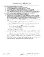
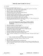
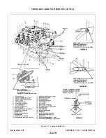
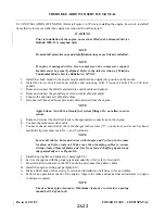
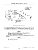
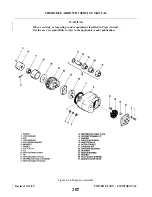
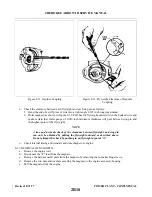
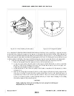
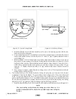
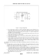
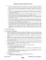
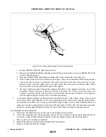
8-21. REPLACEMENT OF ENGINE SHOCK MOUNTS. (Refer to Figure 8-6.)
a.
Remove the engine cowling per Paragraph 8-5.
b. Relieve the engine weight on the mounts using a one-half ton hoist attached to the engine lifting
points.
c.
Remove the four engine mounting bolts and the lower half of the mount assemblies.
d. Carefully raise the engine just enough to remove the shock mounts. Check all lines, wires and cables
for interference. Disconnect any lines and cables if necessary.
e.
Check all components for wear, damage or cracks and install new mounting kit.
f.
Lower the engine slowly and use mounting bolts to keep the components aligned.
g. When the engine is supported by the mount, check the mounts for proper seating.
h. Install the mounting bolt, nut, washer and torque 450 to 500 inch-pounds and safety.
i.
Reconnect any lines, wires or cables that were disconnected and install engine cowling.
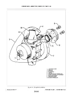
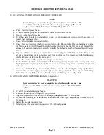
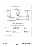
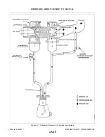
8-22. TURBOCHARGER. The turbocharger system consists of a turbine and compressor assembly, ground
adjustable exhaust bypass screw and the necessary hose and engine air intake ducts. The ground adjustable
exhaust bypass screw allows exhaust gas to bypass the turbine and flow directly overboard. In the closed
position, the bypass screw diverts the exhaust gases into the turbine. The turbocharger requires little attention
between overhauls. However, it is recommended that the items outlined in the Inspection Report, Section III be
checked periodically.
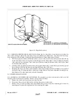
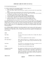
8-22a. TURBOCHARGER NOMENCLATURE. Many unfamiliar terms may appear on the following pages of
this manual. An understanding of these will be helpful, if not necessary, in performing maintenance and
troubleshooting. The following is a list of commonly used terms and names as applied to turbocharging and a
brief description.
TERM
MEANING
Supercharge
To increase the air pressure (density) above or higher than ambient
conditions.
Supercharger
A device that accomplishes the increase in pressure.
Turbo-supercharger
More commonly referred to as a “Turbocharger” this device is driven
by a turbine. The turbine is spun by energy extracted from the engine
exhaust gas.
Compressor
The portion of a turbocharger that takes in ambient air and
compresses it before discharging it to the engine.
Turbine
The exhaust driven end of the turbocharger unit.
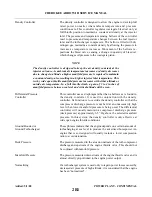
Wastegate and Actuator
The wastegate is a butterfly type valve in the exhaust by-pass which,
(Exhaust By-Pass)
throughout its travel from open to closed, allows varied amounts of
exhaust gas to by-pass the turbine, controlling its speed, hence the
output of the compressor. The actuator is operated by a hydraulic
piston operated by engine oil and cylinder with the piston linked to an
arm on the butterfly valve shaft.
Added: 5/1/80
2A24
CHEROKEE ARROW III SERVICE MANUAL
POWER PLANT - CONTINENTAL
Summary of Contents for ARROW III
Page 4: ...THIS PAGE INTENTIONALLY LEFT BLANK 1A4...
Page 12: ...THIS PAGE INTENTIONALLY LEFT BLANK 1A12...
Page 94: ...Figure 4 2 Wing Installation Revised 2 13 89 1D22 CHEROKEE ARROW III SERVICE MANUAL STRUCTURES...
Page 171: ...lH3 INTENTIONALLY LEFT BLANK...
Page 172: ...lH4 INTENTIONALLY LEFT BLANK...
Page 286: ...THIS PAGE INTENTIONALLY LEFT BLANK Revised 2 13 89 2A8...
Page 528: ...INTENTIONALLY LEFT BLANK 2K10 THRU 2L24 2K10...

