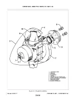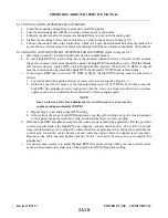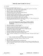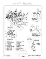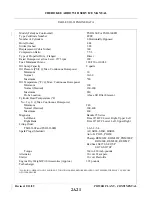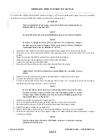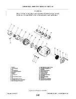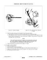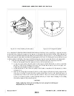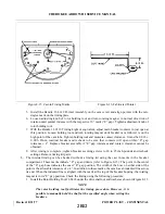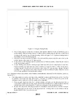
d. Place turbine housing insulation blanket in proper position and safety blanket to turbocharger attaching
hardware.
e.
Position the exhaust tailpipe and exhaust bypass screw to the turbine outlet, aligning the tailpipe with
the hole cut out in the lower cowl provided for it.
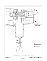
NOTE
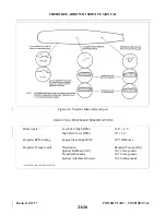
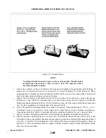
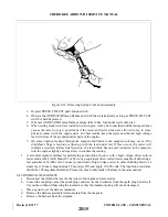
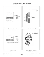
Check the position of the exhaust bypass adjustment screw. If 8 minimum, 9
maximum threads are showing, below jam nut no adjustment is required.
(See Figure 8-36).
f.
Tighten both turbine housing inlet clamps. (Refer to above note on tightening V-band clamps).
g. Position the engine induction tube to turbocharger compressor outlet connector and the induction air
inlet tube to the turbocharger compressor inlet connector in their proper locations and tighten the
clamps.
h. Connect the oil supply and return lines to the turbocharger center housing. Connect the oil pressure
cockpit gauge line if it was previously disconnected.
i.
Perform engine ground run-up and check for normal engine functioning, excessive exhaust manifold
leakage and oil leaks. Repair as necessary.
j.
Install the upper cowling.
8-25. ADJUSTMENT OF TURBOCHARGER. (Refer to Paragraph 8-61, Step b)
NOTE
A complete inspection of the power plant system should be performed before
any turbo adjustments are made.
8-26. OVERBOOST VALVE.
8-27. REMOVAL OF OVERBOOST VALVE.
a.
Remove the four self-locking nuts, plain washers and bolts.
b. Lift the overboost valve assembly from the induction tube.
c.
Remove the O-ring from the seating surface of the overboost mounting flange on the induction tube.
8-28. INSTALLATION OF OVERBOOST VALVE.
a.
Install a new O-ring on the overboost mounting flange of the induction tube.
b. Position the overboost valve assembly on the mounting flange with the holes in the valve aligning with
the holes in the flange.
c.
Install the four bolts and secure with plain washers and self-locking nuts.
8-29. INDUCTION SYSTEM AIR FILTER.
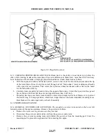
8-30. REMOVAL OF AIR FILTER. (Refer to Figure 8-8.)
a.
Remove the upper cowl.
b. Release the stud fasteners; remove the filter cover and withdraw the filter element.
Revised: 8/31/77
2B4
CHEROKEE ARROW III SERVICE MANUAL
POWER PLANT - CONTINENTAL
Summary of Contents for ARROW III
Page 4: ...THIS PAGE INTENTIONALLY LEFT BLANK 1A4...
Page 12: ...THIS PAGE INTENTIONALLY LEFT BLANK 1A12...
Page 94: ...Figure 4 2 Wing Installation Revised 2 13 89 1D22 CHEROKEE ARROW III SERVICE MANUAL STRUCTURES...
Page 171: ...lH3 INTENTIONALLY LEFT BLANK...
Page 172: ...lH4 INTENTIONALLY LEFT BLANK...
Page 286: ...THIS PAGE INTENTIONALLY LEFT BLANK Revised 2 13 89 2A8...
Page 528: ...INTENTIONALLY LEFT BLANK 2K10 THRU 2L24 2K10...

