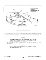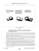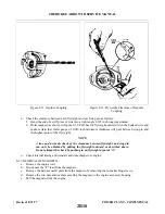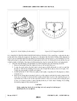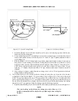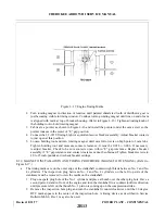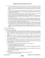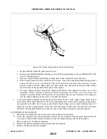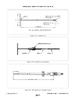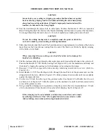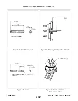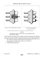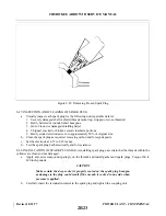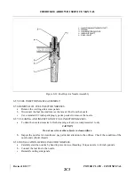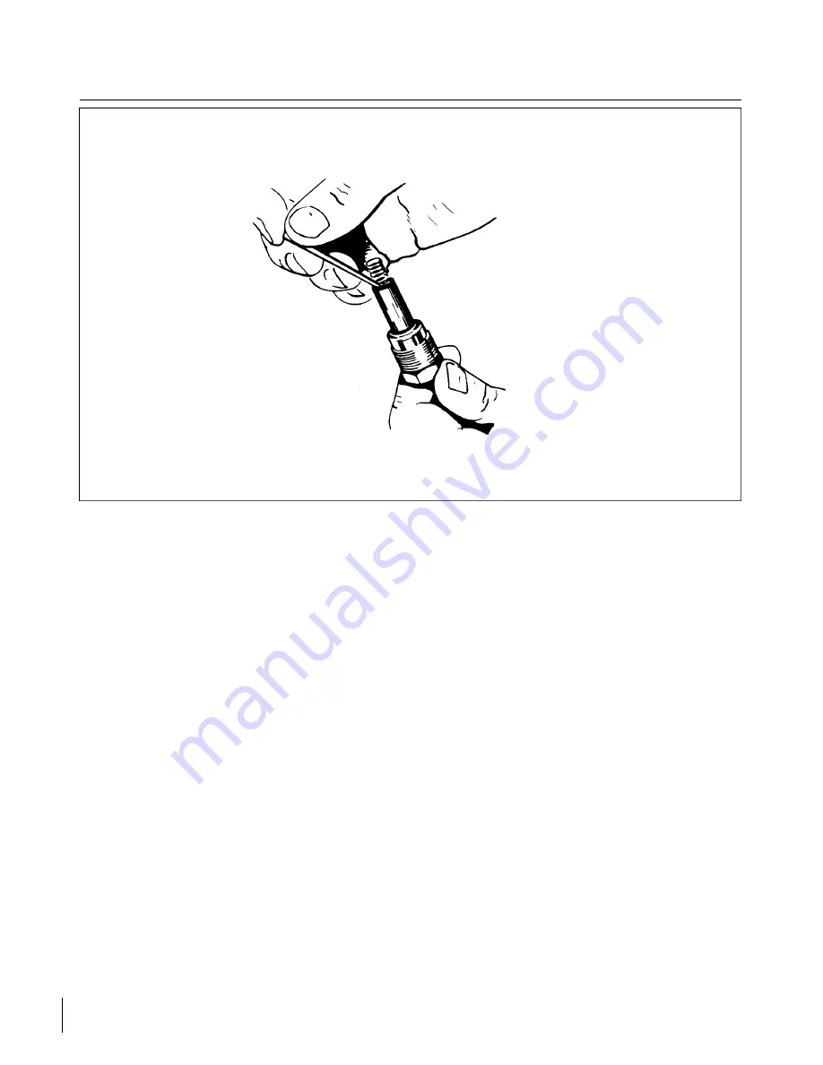
Figure 8-18. Removing Spring From Lead Assembly
3. Depress PRESS-TO-TEST push-button switch.
4. Observe that INDICATOR lamp flashes and GAP fires intermittently as long as PRESS-TO-TEST
switch is held depressed.
5. Whenever INDICATOR lamp flashes and gap fails to fire, lead under test is defective.
6. When testing leads which are installed on an engine, it may be found that distributed capacitance
causes the tester to reject good leads if the tester and red test lead are allowed to lay in close
physical contact with the engine parts. For best results, keep the tester and the red high voltage
lead well clear of the grounded metal parts of the engine.
7. On some engines, leakage through the magneto distributor to the magneto coil may occur if the
distributor finger electrode is lined up with the lead under test. If this occurs, the tester will
indicate a rejection. Before final rejection of a lead which has one end connected to the magneto,
turn the engine slightly and repeat test to confirm the reading.
f.
A second acceptable method for performing an insulation check is with a high voltage, direct current
tester such as the TAKK Model 86 or 86A or an equivalent direct current tester capable of delivering a
test potential of 10,000 volts. Connect ground lead of high voltage tester to outer shielding braid of a
single lead. Connect plug terminal. Turn tester ON and apply 10,000 volts. The insulation resistance
should be 100 megohms minimum. Proceed to check other leads of harness in the same manner.
8-42. REMOVAL OF HARNESS.
a.
Disconnect the clamps that secure the wires to the engine and accessories.
b. Loosen the coupling nuts at the spark plugs and remove the insulators from the spark plug barrel well.
Use caution when withdrawing the insulator so that the insulator spring will not be damaged.
c.
Place a guard over the harness insulators.
d. Remove the harness assembly terminal plate from the magneto.
e.
Remove the harness from the airplane.
Revised: 8/31/77
2B15
CHEROKEE ARROW III SERVICE MANUAL
POWER PLANT - CONTINENTAL
Summary of Contents for ARROW III
Page 4: ...THIS PAGE INTENTIONALLY LEFT BLANK 1A4...
Page 12: ...THIS PAGE INTENTIONALLY LEFT BLANK 1A12...
Page 94: ...Figure 4 2 Wing Installation Revised 2 13 89 1D22 CHEROKEE ARROW III SERVICE MANUAL STRUCTURES...
Page 171: ...lH3 INTENTIONALLY LEFT BLANK...
Page 172: ...lH4 INTENTIONALLY LEFT BLANK...
Page 286: ...THIS PAGE INTENTIONALLY LEFT BLANK Revised 2 13 89 2A8...
Page 528: ...INTENTIONALLY LEFT BLANK 2K10 THRU 2L24 2K10...

