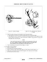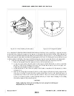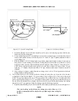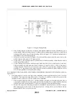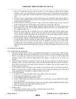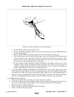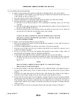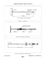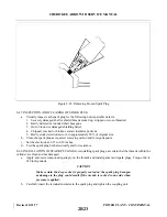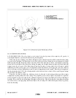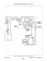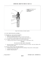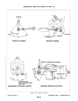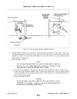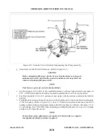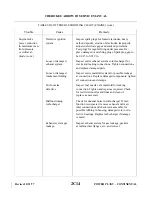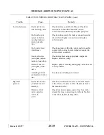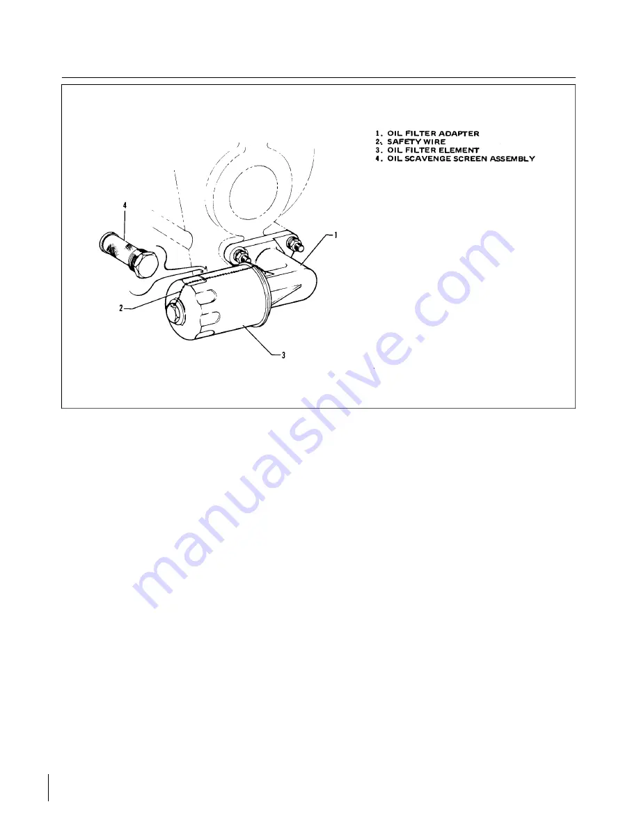
Figure 8-30. Lubrication System Maintenance Points.
8-49. LUBRICATION SYSTEM.
8-50. DESCRIPTION. The oil system is a wet sump, force feed system with a capacity of 8 quarts. A
conventional dipstick is provided for determining the oil quantity.
When the engine is running, oil is drawn through a screen and pick up tube which extends from the sump
to a port in the crankcase. Oil then flows to the inlet of the gear type, engine driven oil pump and is forced
under pressure through the pump outlet. A pressure relief valve prevents excessive oil pressure by allowing
excess oil to be returned to the sump. After leaving the pump, the oil under pressure enters a full flow filter and
is passed onto the oil cooler. If the filter element becomes blocked, a bypass relief valve will open to permit
unfiltered oil to flow to the engine. An oil temperature control unit allows oil to bypass the oil cooler when the
oil is cold. Some oil flows through the cooler to prevent congealing in cold weather. When the oil temperature
reaches approximately 170°F, the oil temperature control unit actuates to close off the cooler bypass forcing
the oil to flow through the cooler.
From the oil cooler oil enters the crankcase where it is directed to the bearing surfaces and other engine
components requiring lubrication and cooling. The propeller governor boost engine oil pressure for operation
of the propeller. A tap in the side of the crankcase supplies oil pressure for lubrication of the turbocharg e r
bearings. Oil is carried to the turbocharger through an external line. After lubricating the turbocharger bearings
it is drawn into a scavenge pump and forced back to the oil sump. Oil within the engine drains, by gravity,
back into the sump.
Revised: 8/31/77
2B24
CHEROKEE ARROW III SERVICE MANUAL
POWER PLANT - CONTINENTAL
Summary of Contents for ARROW III
Page 4: ...THIS PAGE INTENTIONALLY LEFT BLANK 1A4...
Page 12: ...THIS PAGE INTENTIONALLY LEFT BLANK 1A12...
Page 94: ...Figure 4 2 Wing Installation Revised 2 13 89 1D22 CHEROKEE ARROW III SERVICE MANUAL STRUCTURES...
Page 171: ...lH3 INTENTIONALLY LEFT BLANK...
Page 172: ...lH4 INTENTIONALLY LEFT BLANK...
Page 286: ...THIS PAGE INTENTIONALLY LEFT BLANK Revised 2 13 89 2A8...
Page 528: ...INTENTIONALLY LEFT BLANK 2K10 THRU 2L24 2K10...

