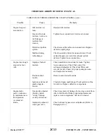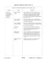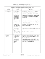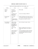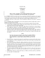
d. Check and Adjustment of Idle Fuel Pressure:
NOTE
The following setup procedure is accomplished with the boost pump OFF
and the engine thoroughly warmed up.
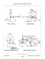
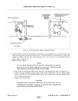
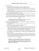
1. Back off the idle speed adjusting screw two turns. (Refer to Figure 8-34.)
2. Start engine and warm up at 1,500 to 1,800 RPM until the oil pressure is in the green arc,
cylinder head temperature is in the lower one quarter of the green arc, and the oil temperature is 160°
to 180° F.
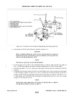
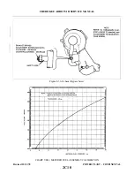
3. While maintaining 700 ± 25 RPM, set the idle fuel pressure at 6.5 ± 0.25 psi by adjusting the idle
pump adjustment screw (refer to Figure 8-35, item 6); clockwise adjustment increases pressure;
counterclockwise adjustment decreases pressure.
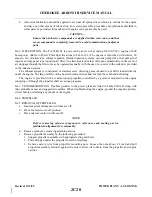
e.
Check and Adjustment of Idle Mixture: (Refer to Figure 8-34.)
1. Operate the engine at 1,500 to 1,800 RPM until cylinder head temperature is in the lower one
quarter of the green arc, and the oil temperature is 160° to 180°F.
2. Reduce the engine speed and stabilize it at 700 ± 25 RPM.
3. Slowly, but positively, move the mixture control from the full rich position to the idle cut-off. The
engine speed should increase 75 to 100 RPM before beginning to drop toward zero (Upper
cowling removed).
4. If the engine speed increase is less than 75 RPM, adjust the idle mixture adjustment to enrich the
mixture (counterclockwise). If the engine speed increase is more than 100 RPM, adjust the idle
mixture to lean the mixture (clockwise). Recheck the adjustment as outlined in Step 3, to insure
the idle mixture is adjusted within limits specified.
f.
Check and Adjustment of Idle Speed: (Refer to Figure 8-34.)
1. With the idle fuel pressure and idle mixture set in accordance with instructions given in Steps “d”
and “e,” cylinder head temperature in the lower one-quarter of the green arc, and oil temperature at
160° to 180°F, set engine speed at 700 + 25 RPM and wait till it stabilizes.
2. Adjust the idle speed adjusting screw until contact is made with the throttle arm stop.
NOTE
After final adjustment, recheck the idle fuel pressure, mixture and speed to
ascertain that all are within specifications given in previous steps.
Revised 12/11/78
2C7
CHEROKEE ARROW III SERVICE MANUAL
POWER PLANT - CONTINENTAL
Summary of Contents for ARROW III
Page 4: ...THIS PAGE INTENTIONALLY LEFT BLANK 1A4...
Page 12: ...THIS PAGE INTENTIONALLY LEFT BLANK 1A12...
Page 94: ...Figure 4 2 Wing Installation Revised 2 13 89 1D22 CHEROKEE ARROW III SERVICE MANUAL STRUCTURES...
Page 171: ...lH3 INTENTIONALLY LEFT BLANK...
Page 172: ...lH4 INTENTIONALLY LEFT BLANK...
Page 286: ...THIS PAGE INTENTIONALLY LEFT BLANK Revised 2 13 89 2A8...
Page 528: ...INTENTIONALLY LEFT BLANK 2K10 THRU 2L24 2K10...

