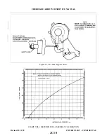
h. Anti-seize lubrication should be applied to all loose-fit spline drives which are external to the engine
and have no other means of lubrication. For certain assembly procedures, molybdenum disulfide in
either paste or powdered form mixed with engine oil or grease may be used.
—CAUTION—
Ensure that Anti-seize compounds are applied in thin even coats, and that
excess compound is completely removed to avoid contamination of adjacent
parts.
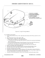
8A-2. DESCRIPTION. The PA-28R-201 is powered by an Av c o - Lycoming IO-360-C1C6 engine of 200
h o r s e p o w e r. (Refer to Power Plant Specifications in Table II-I.) The engine is furnished with starter, 60
ampere, 14-volt alternator, voltage regulator, shielded ignition systems, vacuum pump drive, fuel pump, fuel
injector and dry paper type induction air filter. An alternate air door that will open automatically in the event of
air stoppage through the filter or may be operated manually with the use of a control in the cockpit is provided
in the induction system.
The exhaust system is constructed of stainless steel, directing gases inboard to a muffler located directly
under the engine. The large muffler with a heater shroud provides heat for both the cabin and defrosting.
The engine is provided with a constant speed propeller controlled by a governor mounted on the engine
supplying oil through the propeller shaft at various pressures.
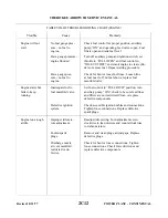
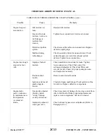
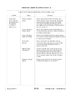
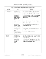
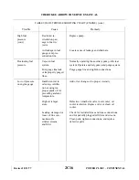
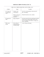
8A-3. TROUBLESHOOTING. Troubles peculiar to the power plant are listed in Table VIIIA-II along with
their probable causes and suggested remedies. When troubleshooting the engine, ground the magneto primary
circuit before performing any checks of the engine.
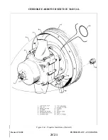
8A-4. PROPELLER.
8A-5. REMOVAL OF PROPELLER.
a.
Insure master and magneto switches are off.
b. Move fuel selector to off position.
c.
Place mixture control in idle cut-off.
NOTE
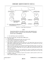
Before removing spinner components, reference each mating part to
facilitate in alignment for reassembly.
d. Remove spinner by removing attaching screws.
e.
Remove propeller assembly by the following procedure:
1. Support propeller assembly with appropriate sling and hoist.
2. Place drip pan under the propeller to catch oil spillage.
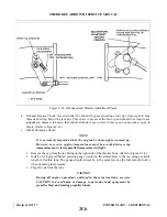
3. Remove safety wire from propeller mounting nuts. Loosen the nuts about 1/4 inch and pull
propeller assembly forward against the nuts to allow oil to drain from the propeller and engine
cavities.
Revised: 2/13/89
2C20
CHEROKEE ARROW III SERVICE MANUAL
POWER PLANT - LYCOMING
Summary of Contents for ARROW III
Page 4: ...THIS PAGE INTENTIONALLY LEFT BLANK 1A4...
Page 12: ...THIS PAGE INTENTIONALLY LEFT BLANK 1A12...
Page 94: ...Figure 4 2 Wing Installation Revised 2 13 89 1D22 CHEROKEE ARROW III SERVICE MANUAL STRUCTURES...
Page 171: ...lH3 INTENTIONALLY LEFT BLANK...
Page 172: ...lH4 INTENTIONALLY LEFT BLANK...
Page 286: ...THIS PAGE INTENTIONALLY LEFT BLANK Revised 2 13 89 2A8...
Page 528: ...INTENTIONALLY LEFT BLANK 2K10 THRU 2L24 2K10...

