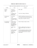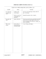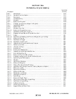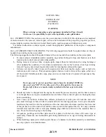
n. Connect the oil cooler.
o. Connect the magneto “P” leads. Check that magneto switch is “OFF.”
p. Connect the fuel pump supply and vent line.
q. Install the injector.
r. Connect the throttle and mixture cables to the injector. Check adjustment of the control by referring to
s. Connect the heater hose to the muffler.
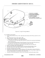
t. Install the air filter box, filter and box cover. Check adjustment of the alternate air door by referring to
u. Connect the governor control cable and secure with clamps.
v. Connect the starter positive and ground leads and secure cables with clamps.
w. Secure the ignition harness, lines, hoses, wires, etc., that may be loose.
x. Install the propeller. (Refer to Paragraph 8A-7.)
y. Install the cowling by attaching the bottom cowl to the firewall and then installing the top. Connect the
electrical lead to the landing light.
z. Connect the gear door retraction rods and secure with bolts, washers and nut.
NOTE
To avoid possible high speed bearing failure resulting from a lack of
lubrication during initial starts, the engine should be pre-oiled in
accordance with the latest revision of Lycoming Service Instruction No.
1241.
aa. Install the proper grade and amount of engine oil.
ab. Turn on the fuel valve; open the throttle full and turn on the electric fuel pump. Check the fuel lines for
leaks.
ac. Perform an engine operational check.
8A-15a. INSTALLATION OF OIL COOLER.
a. When installing fittings in the oil coolers, care should be used to prevent excessive torque being
applied to the cooler. When a rectangular fitting boss is provided, a backup wrench should be used,
employing a scissors motion, so that no load is transmitted to the cooler. When the oil cooler has a
round fitting boss, care should be taken not to permit excessive torque on the fittings.
b. If a pipe thread fitting is used, it should be installed only far enough to seal with sealing compound.
c. Apply Lubon No. 404 to all male pipe thread fittings; do not allow sealant to enter the system.
d. If fitting cannot be positioned correctly using a torque of 10 to 15 foot-pounds, another fitting should
be used.
e. When attaching lines to the cooler, a backup wrench should be used.
f. After installation, inspect the cooler for distorted end cups.
g. Run-up engine. After run-up, check for oil leaks.
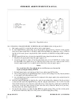
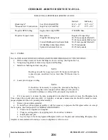
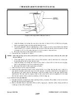
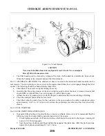
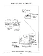
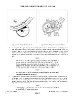
8A-16. ADJUSTMENT OF THROTTLE AND MIXTURE CONTROLS. (Refer to Figure 8A4a.) Throttle and
mixture controls are adjusted so that when the throttle arm on the fuel injector is rotated forward against its full
throttle stop and the mixture control is rotated forward against its full rich stop, the cockpit control levers of
the throttle and mixture should have 0.010 to 0.030 of an inch spring back on instrument panel stop when in
full throttle or full rich position.
a. The throttle may be adjusted as follows:
1. At the fuel injector, disconnect the rod end of the throttle control cable from the control arm.
Loosen the jam nut that secures the rod end.
Revised: 11/21/80
2D6
CHEROKEE ARROW III SERVICE MANUAL
POWER PLANT - LYCOMING
Summary of Contents for ARROW III
Page 4: ...THIS PAGE INTENTIONALLY LEFT BLANK 1A4...
Page 12: ...THIS PAGE INTENTIONALLY LEFT BLANK 1A12...
Page 94: ...Figure 4 2 Wing Installation Revised 2 13 89 1D22 CHEROKEE ARROW III SERVICE MANUAL STRUCTURES...
Page 171: ...lH3 INTENTIONALLY LEFT BLANK...
Page 172: ...lH4 INTENTIONALLY LEFT BLANK...
Page 286: ...THIS PAGE INTENTIONALLY LEFT BLANK Revised 2 13 89 2A8...
Page 528: ...INTENTIONALLY LEFT BLANK 2K10 THRU 2L24 2K10...

