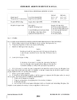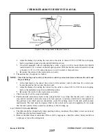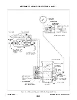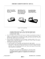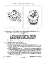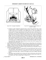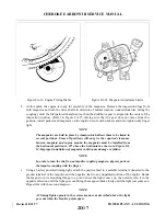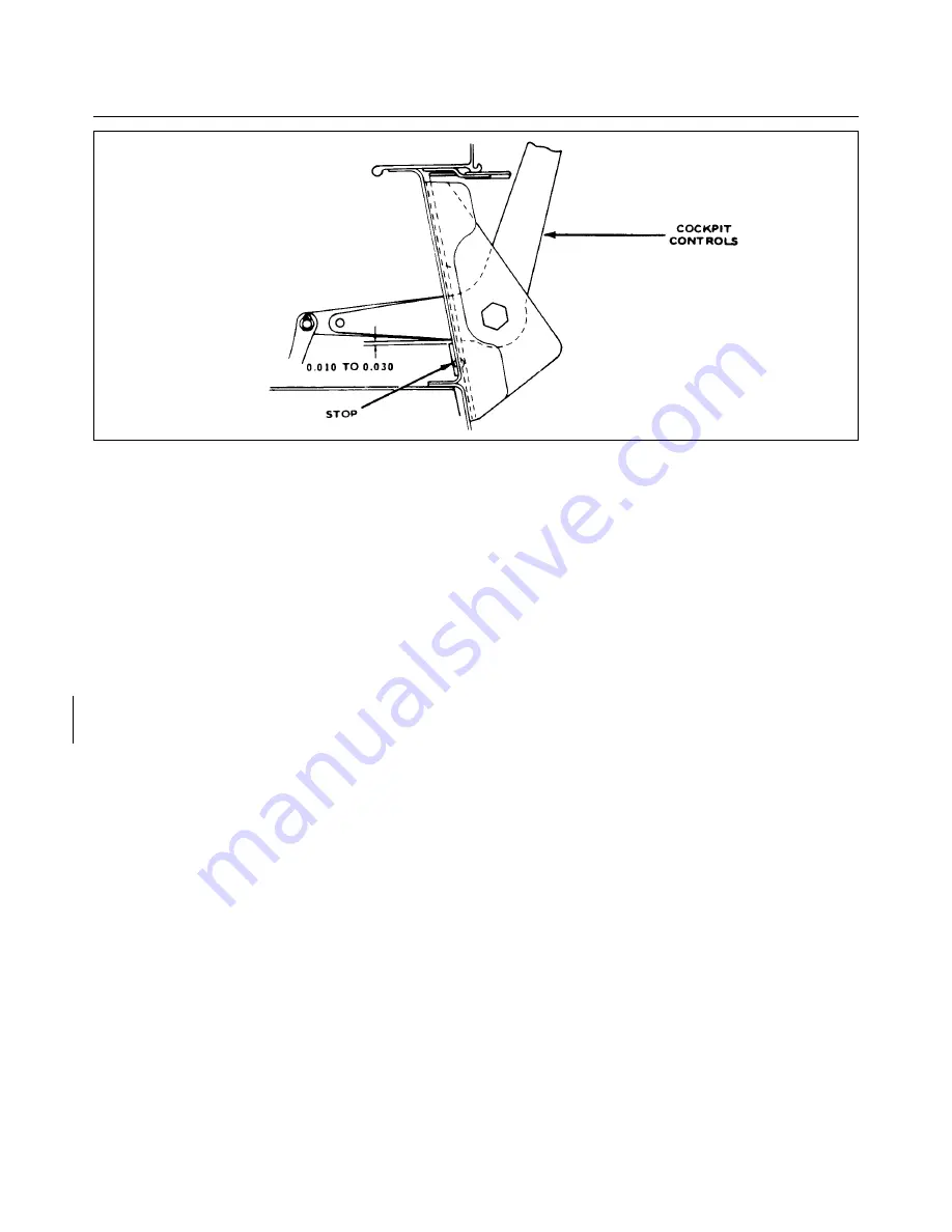
2. Adjust the linkage by rotating the rod end on the cable to obtain 0.010 to 0.030O fan inch spring
back on instrument panel stop when in full throttle position.
3. On aircraft equipped with air conditioning systems, a micro switch is located below the throttle
control which is set to actuate in the full open position. With the throttle control adjusted to obtain
a clearance of .010 to .030, adjust the micro switch to actuate at this point also.
4. Reconnect the rod end to the control arm and safety.
b. The mixture may be adjusted as follows:
NOTE: Check the routing and security of the mixture cable to prevent interference between the cable and
the gear linkage.
1. At the fuel injector, disconnect the rod end of the mixture control cable from the control arm.
Loosen the jam nut that secures the clevis end.
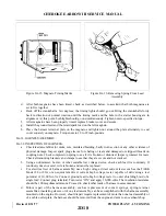
2. Adjust the linkage by rotating the rod end on the cable to obtain 0.010 to 0.030 of an inch spring
back on the instrument stop when in full rich position.
3. Reconnect the rod end to the control arm and safety.
c. Check security of cable casing attachments.
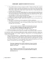
d. Pull the throttle and mixture levers in the cockpit full aft to ascertain that the idle screw contacts its
stop and the mixture control arm contacts its lean position. A mixture control lock is incorporated in
the quadrant cover which prevents the mixture control from being moved to the idle cutoff position
inadvertently. The lock must be depressed before the control can be moved completely aft. Ascertain
that the lock operates freely without any tendency to bind or hang up.
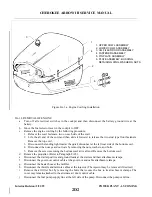
8A-17. INDUCTION AIR FILTER.
a. The filter should be cleaned daily when operating in dusty conditions. If any holes or tears are noticed,
the filter must be replaced immediately.
b. Remove the filter element and shake off loose dirt by rapping on a hard flat surface, being careful not
to damage or crease the sealing ends.
Revised: 02/27/04
2D7
CHEROKEE ARROW III SERVICE MANUAL
POWER PLANT - LYCOMING
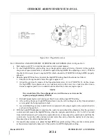
Figure 8A4a. Adjustment of Engine Controls
Summary of Contents for ARROW III
Page 4: ...THIS PAGE INTENTIONALLY LEFT BLANK 1A4...
Page 12: ...THIS PAGE INTENTIONALLY LEFT BLANK 1A12...
Page 94: ...Figure 4 2 Wing Installation Revised 2 13 89 1D22 CHEROKEE ARROW III SERVICE MANUAL STRUCTURES...
Page 171: ...lH3 INTENTIONALLY LEFT BLANK...
Page 172: ...lH4 INTENTIONALLY LEFT BLANK...
Page 286: ...THIS PAGE INTENTIONALLY LEFT BLANK Revised 2 13 89 2A8...
Page 528: ...INTENTIONALLY LEFT BLANK 2K10 THRU 2L24 2K10...

