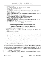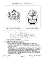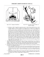
3. Secure distributor block to housing with studs and washers. Tighten studs finger tight. Loosen the
11-8465 Rotor Holding Tool and turn rotating magnet in reverse direction of rotation until timing
light indicates contact assembly had just opened and check to make certain timing marks align
within tolerance indicated above. Tighten block securing studs, first to 4-8 inch-pounds torque and
then final torque to 20 inch-pounds.
4. Insert the tip of your small finger through timing hole in housing and against large distributor gear
teeth. Rock distributor gear back and forth slightly. There must be perceptible backlash between
teeth of large and small gears. This check should be made at three different points, 120° apart on
gear. If backlash is not evident, replace large distributor gear.
5. Install the breaker cover and complete reassembly of the magneto. Refer to the manufacturer’s
publications for complete disassembly and reassembly procedures.
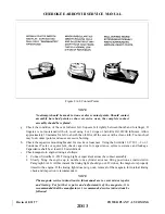
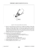
e. On the magneto employing the impulse coupling, check clearance between each flyweight and each
stop pin as follows:
1. Bend the end of a stiff piece of wire into a right angle 1/8 inch long (maximum).
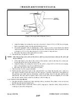
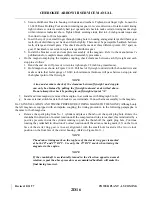
2. Hold magneto as shown in Figure 8A-12. Pull heel of flyweight outward with the hooked wire and
make certain that feeler gauge of 0.010 inch minimum thickness will pass between stop pin and
the highest point of the flyweight.
NOTE
A true and accurate check of the clearance between flyweight and stop pin
can only be obtained by pulling the flyweight outward as described above.
Do not attempt the check by pushing in on flyweight at point “A.”
f. Install and time magneto, removed from engine, in accordance with Paragraph 8A-30.
g. Secure external switch leads to the breaker cover terminals. Connect harness assembly to the magneto.
8A-30. INSTALLATION AND TIMING PROCEDURE (TIMING MAGNETO TO ENGINE). Although only
the left magneto is equipped with an impulse coupling, the timing procedure, in the following paragraphs, is
the same for both magnetos.
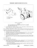
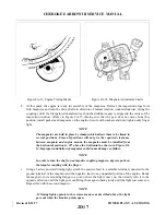
a. Remove the spark plug from No. 1 cylinder and place a thumb over the spark plug hole. Rotate the
crankshaft in direction of normal rotation until the compression stroke is reached, this is indicated by a
positive pressure inside the cylinder tending to push the thumb off the spark plug hole. Continue
rotating the crankshaft in direction of normal rotation until the advance timing mark (25) on the front
face of the starter ring gear is in exact alignment with the small hole located at the two o’clock
position on the front face of the starter housing. (Refer to Figure 8A-13.)
NOTE
The advance timing mark on the top face of the starter ring gear is marked
at both 20° and 25° BTC. Use only the 25° BTC mark when timing the
magnetos to the engine.
NOTE
If the crankshaft is accidentally turned in the direction opposite normal
rotation, repeat the above procedure as accumulated backlash will make the
final timing incorrect.
Revised: 8/31/77
2D16
CHEROKEE ARROW III SERVICE MANUAL
POWER PLANT - LYCOMING
Summary of Contents for ARROW III
Page 4: ...THIS PAGE INTENTIONALLY LEFT BLANK 1A4...
Page 12: ...THIS PAGE INTENTIONALLY LEFT BLANK 1A12...
Page 94: ...Figure 4 2 Wing Installation Revised 2 13 89 1D22 CHEROKEE ARROW III SERVICE MANUAL STRUCTURES...
Page 171: ...lH3 INTENTIONALLY LEFT BLANK...
Page 172: ...lH4 INTENTIONALLY LEFT BLANK...
Page 286: ...THIS PAGE INTENTIONALLY LEFT BLANK Revised 2 13 89 2A8...
Page 528: ...INTENTIONALLY LEFT BLANK 2K10 THRU 2L24 2K10...

